


TROUBLESHOOTING & REPAIR
F-49 F-49
COMMANDER 500
Return to Section TOC Return to Section TOC Return to Section TOC Return to Section TOC
Return to Master TOC Return to Master TOC Return to Master TOC Return to Master TOC
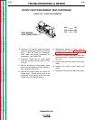
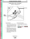
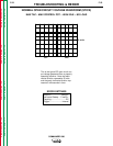
DIODE
MODULE
TERMINALS
HEAT SINK
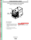
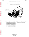
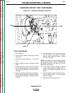
FIGURE F.23 – DIODE MODULE TEST
POWER MODULE TEST (CONTINUED)
Check Diode Module
9. Using the analog ohmmeter, connect the
negative meter probe to the terminal on the
diode module. See Figure F.23. Connect
the positive meter probe to the heat sink.
The resistance should be very high (over
50,000 ohms).
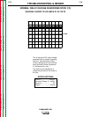
10. Using the analog ohmmeter, connect the
positive meter probe to the terminal on the
diode module. Connect the negative meter
probe to the heat sink. The resistance
should be low (approximately 300 ohms).
Also check diode D3 (right side) or D4 (left
side) for an open or shorted condition. See
the Wiring Diagram.
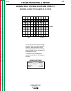
When all tests are complete:
11. Reconnect all leads previously removed.
12. Torque the capacitor nuts to 50-60 inch-
pounds.
13. If finished testing, perform the Case Cover
Replacement procedure.