


TROUBLESHOOTING & REPAIR
F-40 F-40
COMMANDER 500
Return to Section TOC Return to Section TOC Return to Section TOC Return to Section TOC
Return to Master TOC Return to Master TOC Return to Master TOC Return to Master TOC
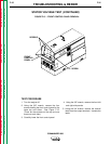
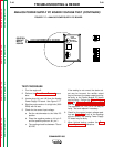
CONTROL
CIRCUIT
INPUT
POWER
13 1J41 to POS TERMINAL ON C2 - 85V SUPPLY
J41
J42
14 2J41 to NEG TERMINAL ON C2 - 85V SUPPLY
PCB2
ANALOG
POWER
PC BOARD
3
2
4
1
10
9
8
7
6
1
2
3
4
5
J41
J42
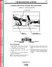
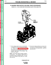
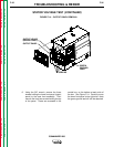
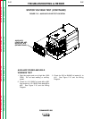
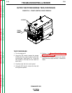
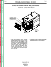
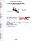
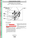
FIGURE F.17 – ANALOG POWER SUPPLY PC BOARD
ANALOG POWER SUPPLY PC BOARD VOLTAGE TEST (CONTINUED)
TEST PROCEDURE
1. Turn the engine off.
2. Perform the Case Cover Removal proce-
dure.
3. Locate plugs J41 and J42 from the Analog
Power Supply PC board. See Figure F.17.
4. Start the engine and run it at high idle (1900
RPM) with no load.
5. Check for the correct input voltage:
a. Set the volt/ohmmeter to the Volts DC
position.
b. Place the negative probe on J41 pin 2
and the positive probe on J41 pin 1.
c. The reading should be between 75 and
85 VDC.
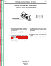
If the reading is not correct, the stator out-
put may be incorrect, the rectifier output
may be incorrect, the power capacitors may
be faulty, or the Power Module PC board
may be faulty. Perform the Stator Voltage
Test, the Output Rectifier Bridge Test,
and the Power Module PC Board Test.
The capacitors C1, C2, C3 or C4 may be
faulty. Test and replace if necessary.
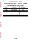
6. Check for the correct output voltage read-
ings per Table F.1. If any of the readings
are not correct, the Analog Power Supply
PC board may be faulty.
7. When finished testing, perform the Case
Cover Replacement procedure.