


TROUBLESHOOTING & REPAIR
F-62 F-62
COMMANDER 500
Return to Section TOC Return to Section TOC Return to Section TOC Return to Section TOC
Return to Master TOC Return to Master TOC Return to Master TOC Return to Master TOC
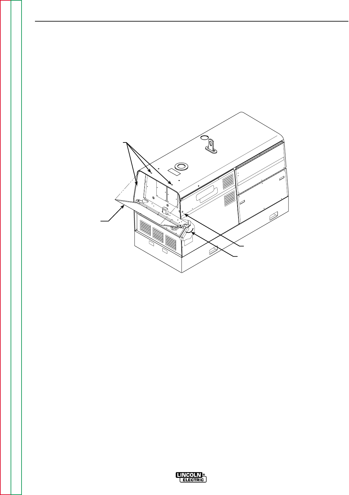
FRONT
CONTROL
PANEL
SCREWS
SCREW
GREEN
GROUND
LEAD
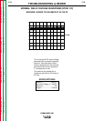
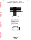
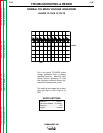
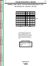
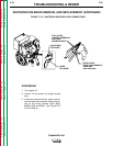
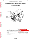
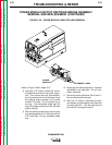
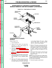
F.27 – CONTROL PANEL REMOVAL
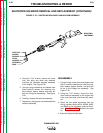
POWER MODULE/OUTPUT RECTIFIER BRIDGE ASSEMBLY
REMOVAL AND REPLACEMENT (CONTINUED)
PROCEDURE
1. Turn the engine off.
2. Using the 3/8" wrench, remove the screws
holding the front control panel to the case
top and sides. See Figure F.27. (There are
two screws on the top and one screw on
each side.)
3. Carefully lower the front control panel.
4. Using the 3/8" wrench, remove the front left
and right side panels.
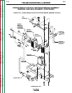
5. Perform the Output Panel Removal section
of the Case Cover Removal procedure.
6. Perform the Power Module Capacitor
Discharge Procedure.
7. Optional: With the 7/16" wrench, remove the
ground wire from the output panel assembly.
If the ground wire is not in the way, it can
remain attached.