


TROUBLESHOOTING & REPAIR
F-59 F-59
POWER WAVE 455/R
Return to Section TOC Return to Section TOC Return to Section TOC Return to Section TOC
Return to Master TOC Return to Master TOC Return to Master TOC Return to Master TOC
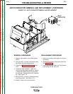
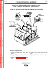
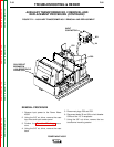
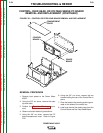
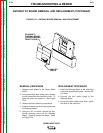
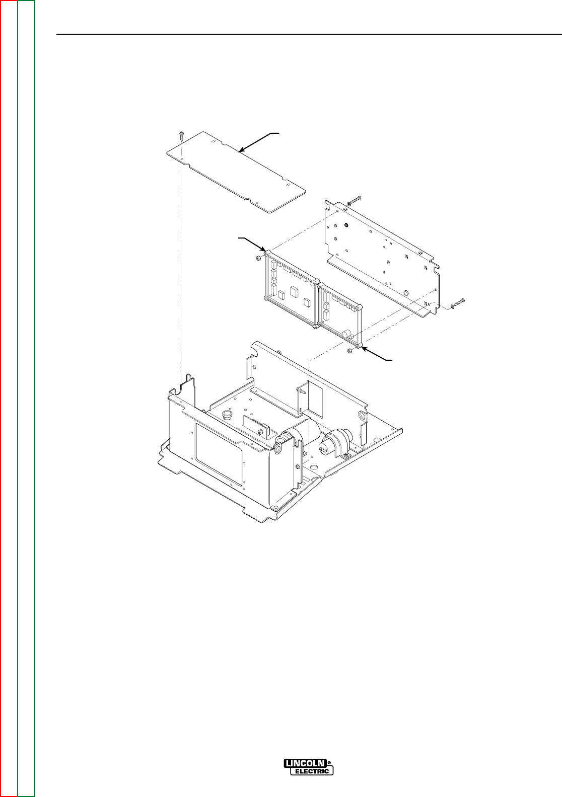
COMPARTMENT
COVER
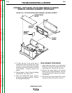
CONTROL
BOARD
POWER
BOARD
FIGURE F.22 – CONTROL OR FEED HEAD BOARD REMOVAL AND REPLACEMENT
CONTROL, FEED HEAD, OR VOLTAGE SENSE PC BOARD
REMOVAL AND REPLACEMENT (CONTINUED)
REMOVAL PROCEDURE
1. Remove input power to the Power Wave
455/R.
2. Using the 3/8” nut driver, remove the case
top and sides.
3. Perform the Capacitor Discharge proce-
dure.
4. Observe all static electricity precautions.
5. Using the 3/8” nut driver, remove the PC
board compartment cover. Refer to Figure
F.22.
6. Using the 3/8” nut driver, remove the two
screws holding the rear of the Control Box in
place.
7. Clear the leads in the sleeving and the grom-
mets on the sides of the control box.
8. Label and remove the molex plugs from the
Control Board and the Feed Head Board.