


TROUBLESHOOTING & REPAIR
F-73 F-73
POWER WAVE 455/R
Return to Section TOC Return to Section TOC Return to Section TOC Return to Section TOC
Return to Master TOC Return to Master TOC Return to Master TOC Return to Master TOC
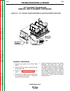
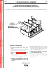
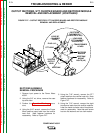
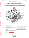
OUTPUT RECTIFIER, STT CHOPPER BOARD AND RECTIFIER MODULE
REMOVAL AND REPLACEMENT (CONTINUED)
RECTIFIER MODULE REMOVAL AND
REPLACEMENT PROCEDURE
1. Using the 9/64” allen wrench, remove the
cap screw from the center of the rectifier
module that is to be replaced.
2. Using the 7/16” wrench, remove the two
mounting bolts and associated washers
from the rectifier module to be replaced.
3. Remove the faulty module.
4. This module requires special mounting con-
siderations to prevent warping of the base
plate. The heat sink surfaces must be clean
and flat. Apply a thin, even coating of ther-
mal compound, (Penetrox A13) 0.004 to
0.010 inches thick. Keep the compound
away from the area of the mounting holes.
5. Press the new module firmly against the
heat sink while aligning the mounting holes.
Start all three screws two to three turns by
hand.
6. Tighten each of the outer screws to between
5 and 10 in-lbs.
7. Tighten the center screw to between 12 and
18 in-lbs.
8. Tighten each of the outer screws again, this
time to between 30 and 40 in/lbs.
RECTIFIER ASSEMBLY REPLACE-
MENT PROCEDURE
1. Position the assembly in place with the
mounting bolts.
2. Assemble the nuts and associated wash-
ers to the mounting bolts.
3. Using the 7/16” wrench, tighten the four
nuts on the mounting bolts.
4. Replace leads #292 and #291 to the ther-
mostat.
5. Connect plug J10 to the STT Chopper
Board.
6. With the 7/16” wrench, attach lead #287
from the STT Snubber Diode D5.
7. With the 7/16” wrench, attach lead #289B
from the STT Snubber Capacitor C10.
8. Connect the eight transformer leads to the
correct rectifier modules. Tighten the
screws (with two flat washers and one lock
washer) to between 30 and 40 in/lbs. Do
not stress the terminals when making
these connections.
9. Apply a thin coat of Penetrox A13 to the
heat sink where the Power Wave positive
output lead and the STT output lead attach.
10. Attach the Power Wave positive output
lead to the heat sink using the 9/16”
wrench.
11. Attach the STT output lead to the heat sink
using the 7/16” wrench.
12. Install the case top and sides using the 3/8”
nut driver.