


TROUBLESHOOTING & REPAIR
F-60 F-60
POWER WAVE 455/R
Return to Section TOC Return to Section TOC Return to Section TOC Return to Section TOC
Return to Master TOC Return to Master TOC Return to Master TOC Return to Master TOC
CONTROL, FEED HEAD, OR VOLTAGE SENSE PC BOARD
REMOVAL AND REPLACEMENT (CONTINUED)
9. Tilt back the rear of the control box to
access the PC board mounting nuts. Using
the 3/8” nut driver, remove the self-locking
mounting nuts from the Control and Feed
Head Boards. Carefully remove the
boards.
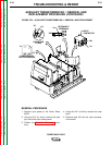
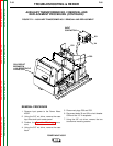
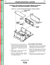
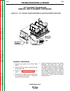
10. Remove plugs J1 and J2 from the Voltage
Sense Board. See Figure F.23.
11. Using the needle-nose pliers, carefully
pinch the three plastic standoffs. Remove
the Voltage Sense Board.
REPLACEMENT PROCEDURE
1. Install either the Control or the Feed Head
Board to the back of the control box with the
self-locking nuts. Use the 3/8” nut driver.
2. Connect the molex plugs to the Control
Board and the Feed Head Board. Be sure
the lead harnesses are securely and proper-
ly positioned.
3. Secure the rear of the control box in place
using two screws and the 3/8” nut driver.
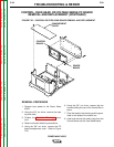
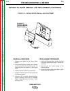
COMPARTMENT
COVER
CONTROL
BOARD
POWER
BOARD
VOLTAGE
SENSE
BOARD
FIGURE F.23 – VOLTAGE SENSE BOARD REMOVAL AND REPLACEMENT