


TROUBLESHOOTING & REPAIR
F-45 F-45
POWER WAVE 455/R
Return to Section TOC Return to Section TOC Return to Section TOC Return to Section TOC
Return to Master TOC Return to Master TOC Return to Master TOC Return to Master TOC
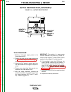
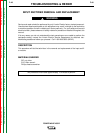
TABLE F.7 – SECONDARY VOLTAGES
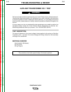
AUXILIARY TRANSFORMER NO. 1 TEST (CONTINUED)
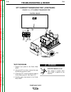
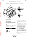
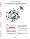
7. Carefully apply the correct input voltage to
the Power Wave 455/R.
ELECTRIC SHOCK can kill.
High voltage is present at prima-
ry of the Auxiliary Transformer.
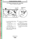
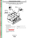
8. Check for the correct secondary voltages
according to Table F.7.
NOTE: The secondary voltages will vary if the
input line voltage varies.
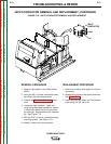
9. If the correct secondary voltages are pre-
sent, the T1 auxiliary transformer is func-
tioning properly. If any of the secondary
voltages are missing or low, check to make
certain the primary is configured correctly
for the input voltage applied. See the
Wiring Diagram.
10. If the correct input voltage is applied to the
primary, and the secondary voltage(s) are
not correct, the T1 transformer may be
faulty.
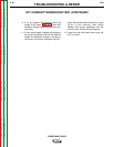
11. Replace any cables ties and insulation
removed earlier.
12. Install the case sides and top using the 3/8”
nut driver.
LEAD IDENTIFICATION
X1 to X2
X3 to X5
X3 to X4
NORMAL EXPECTED VOLTAGE
52 VAC
115 VAC
24 VAC
WARNING