


TROUBLESHOOTING & REPAIR
F-35 F-35
POWER WAVE 455/R
Return to Section TOC Return to Section TOC Return to Section TOC Return to Section TOC
Return to Master TOC Return to Master TOC Return to Master TOC Return to Master TOC
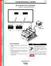
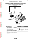
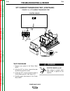
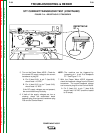
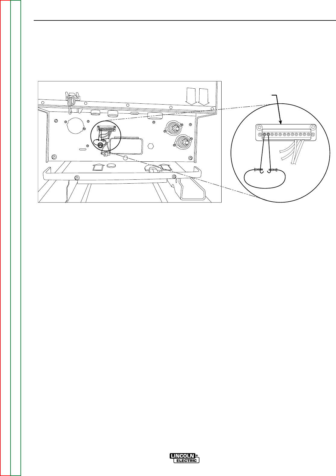
FIGURE F.12 – RECEPTACLE S7 TRIGGERED
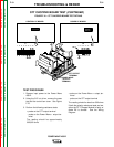
POWER WAVE CURRENT TRANSDUCER TEST (CONTINUED)
RECEPTACLE
S7
STT
POWER
WAVE
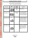
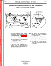
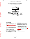
5. Turn on the Power Wave 455/R. Check for
the correct DC supply voltage to the current
transducer at plug J8. See Figure F.11.
A. Pin 2 (lead 212+) to pin 6 (lead 216-)
should read +15 VDC.
B. Pin 3 (lead 213-) to pin 6 (lead 216+)
should read -15 VDC.
If the DC supply voltages are not present,
the control board may be faulty.
6. If both of the supply voltages are low or
missing, check the associated leads
between plug J8 and current transducer plug
P91 and the Control Board.
NOTE: The machine can be triggered by
jumpering pin 1 to pin 2 at receptacle
S7. See Figure F.12.
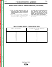
7. With the Power Wave 455/R triggered,
check the feedback voltage from the current
transducer. The current feedback voltage
can be read at plug J8 on the Control Board.
A. Pin 1 (lead 211) to pin 6 (lead 216)
should read 2.0 VDC (machine loaded
to 250 amps).