


TROUBLESHOOTING & REPAIR
F-24 F-24
POWER WAVE 455/R
Return to Section TOC Return to Section TOC Return to Section TOC Return to Section TOC
Return to Master TOC Return to Master TOC Return to Master TOC Return to Master TOC
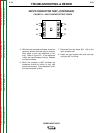
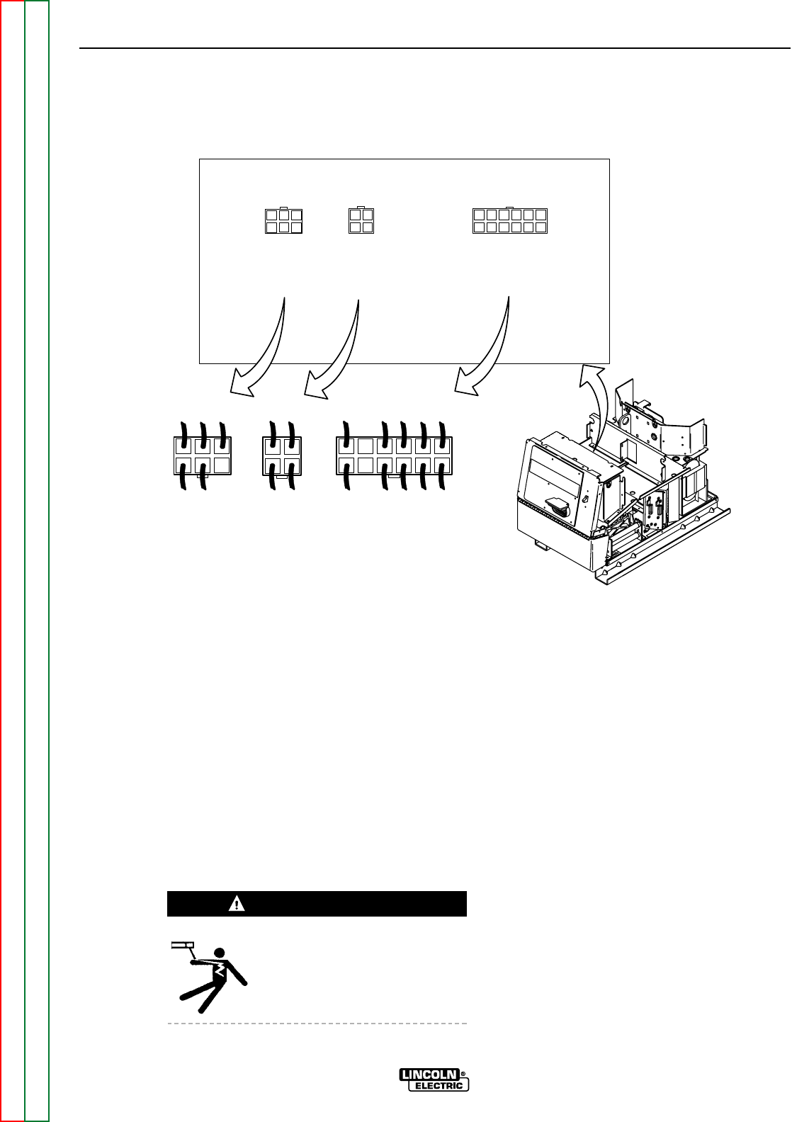
J42
J41
J43
4 5 6
3 4
7 8 9 10 11 12
J42
J41
J43
1 2 3
1 2
1 2 3 4 5 6
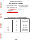
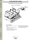
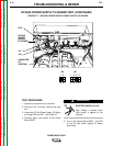
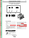
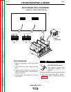
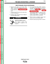
FIGURE F.8 – POWER BOARD TEST
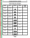
POWER BOARD TEST (CONTINUED)
TEST PROCEDURE
1. Remove input power to the Power Wave
455/R.
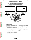
2. Using the 3/8” nut driver, remove the case
top.
3. Perform the Capacitor Discharge
Procedure.
4. Locate the Power Board and plugs J42 and
J43. Do not remove plugs or leads from
the Power Board. Refer to Figure F.8.
5. Carefully apply input power to the Power
Wave 455/R.
ELECTRIC SHOCK can kill.
High voltage is present when
input power is applied to the
machine.
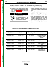
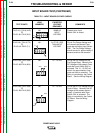
6. Turn on the Power Wave 455/R. Carefully
test for the correct voltages at the Power
Board according to Table F.4.
7. If either of the 40 VDC voltages is low or not
present at plug J41, perform the DC Bus PC
Board Test. See the Wiring Diagram. Also
perform the T1 Auxiliary Transformer Test.
8. If any of the DC voltages are low or not pre-
sent at plugs J42 and/or 43, the Power
Board may be faulty.
9. Install the case top using the 3/8” nut driver.
WARNING