


TROUBLESHOOTING & REPAIR
F-75 F-75
POWER WAVE 455/R
Return to Section TOC Return to Section TOC Return to Section TOC Return to Section TOC
Return to Master TOC Return to Master TOC Return to Master TOC Return to Master TOC
13/14
OR
17/18
NYLON
SCREW
(2X)
19+
20-
11/12
OR
15/16
SWITCH
BOARD
MOLEX PLUG
MOUNTING
SCREW (4X)
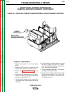
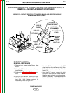
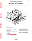
FIGURE F.28 – SWITCH BOARD AND FILTER CAPACITOR REMOVAL AND REPLACEMENT
SWITCH BOARD AND FILTER CAPACITOR
REMOVAL AND REPLACEMENT (CONTINUED)
REMOVAL PROCEDURE
NOTE: Observe all static electricity precautions.
Lead and plug references below use a slash (/)
to indicate machine right side/left side wire
number differences.
1. Remove input power to the Power Wave
455/R.
2. Using the 3/8” nut driver, remove the case
top and sides.
3. Perform the Capacitor Discharge proce-
dure.
4. Using the 5/16” nut driver, remove the three
screws mounting the glastic high voltage
protective shield. Remove the shield.
5. Remove molex plug J40/J50 from the top of
the switch board. Refer to Figure F.28.
6. Remove the mylar insulating shield covering
leads 13/14 or 17/18. Cut the cable tie.