


TROUBLESHOOTING & REPAIR
F-72 F-72
POWER WAVE 455/R
Return to Section TOC Return to Section TOC Return to Section TOC Return to Section TOC
Return to Master TOC Return to Master TOC Return to Master TOC Return to Master TOC
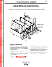
OUTPUT RECTIFIER, STT CHOPPER BOARD AND RECTIFIER MODULE
REMOVAL AND REPLACEMENT (CONTINUED)
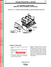
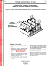
7. Using the needle-nose pliers, remove
leads #292 and #291 from the rectifier ther-
mostat.
8. Disconnect plug J10 from the STT
Chopper Board.
9. With the 7/16” wrench, remove lead #287
from the STT Snubber Diode D5.
10. With the 7/16” wrench, remove lead #289B
from the STT Snubber Capacitor C10.
11. Using the 7/16” wrench, remove the four
nuts and associated washers from the heat
sink mounting bolts. The heat-sink assem-
bly can be removed by carefully sliding the
assembly forward and removing the mount-
ing bolts.
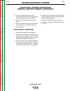
STT CHOPPER BOARD REMOVAL
AND REPLACEMENT PROCEDURE
1. Place the output rectifier assembly on a
clean bench surface.
2. Using a slot head screw driver, remove the
two nylon screws holding the board to the
heat sink. Save the standoffs for reassem-
bly.
3. Using the 7/16” wrench, remove the two
bolts, lock washers and flat washers. Save
the standoffs for reassembly.
4. Using the 3/16” allen wrench, remove the
four screws and lock washers holding the
board to the heat sink.
5. Carefully remove the STT Chopper Board.
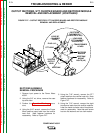
REPLACEMENT PROCEDURE
1. Position the new board on the heat sink,
using the standoffs for the slot head nylon
screws and the allen head screws.
2. Install the four 3/16” allen head screws and
lock washers.
3. Install the two nylon slot head screws.
4. Install the two 7/16” bolts, lock washers and
flat washers.