


TROUBLESHOOTING & REPAIR
F-28 F-28
POWER WAVE 455/R
Return to Section TOC Return to Section TOC Return to Section TOC Return to Section TOC
Return to Master TOC Return to Master TOC Return to Master TOC Return to Master TOC
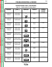
INPUT BOARD TEST(CONTINUED)
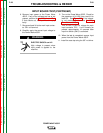
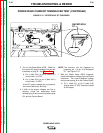
6. Remove input power to the Power Wave
455/R. If any of the voltages are low or not
present, perform the Input Contactor Test.
If that checks out, the Input Board may by
faulty.
7. Reconnect lead X4 to the main input contac-
tor CR1 coil terminal.
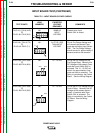
8. Carefully apply the correct input voltage to
the Power Wave 455/R.
ELECTRIC SHOCK can kill.
High voltage is present when
input power is applied to the
machine.
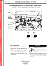
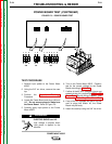
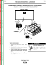
9. Turn on the Power Wave 455/R. Check for
the presence of 24 VAC from lead X4 to
lead 601. See Figure F. 9. If the voltage
is not present, perform the Auxiliary
Transformer #1 Test.
9. This 24 VAC is the coil voltage for main
input contactor CR1. It will normally be
present approximately 12 seconds after
input line switch (SW1) is activated.
10. When the test is completed, remove input
power from the Power Wave 455/R.
11. Install the case top using the 3/8” nut driver.
WARNING