


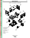
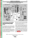

DC BUS BOARD, POWER BOARD,
FEED HEAD BOARD, GATEWAY
BOARD AND VOLTAGE SENSE
BOARD
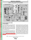
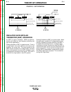
The DC Bus Board receives approximately 65VDC
from the Bus Board rectifier. The DC Bus Board regu-
lates that 65VDC to a +40VDC supply. This regulated
40VDC is applied to the Feed Head Board, the Power
Board, and the wire feeder receptacle.
The switching power supplies on the Power Board sup-
ply a variety of regulated DC voltages to the Control
Board and a +20VDC to the STT Chopper Board. The
Control Board uses these regulated voltages to power
the many circuits and communication functions incor-
porated within the Control Board.
When the Feed Head Board activates the Voltage
Sense Board, the actual arc voltage is sensed (lead
67), and this information is delivered through the volt-
age sense board to the Control Board.
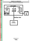
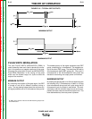
The Power Wave 455R uses two digital communication
platforms. Internally the PC boards communicate via
ArcLink. Externally the Power Wave 455R communi-
cates using the industry standard Device Net protocol.
The Gateway Board makes the translation between the
two platforms possible. The Power Wave 455R does
not have a dedicated interface device or board. The
robot (or other input device – PLC, etc.) acts as the
user interface, issuing commands through the Device
Net protocol that are translated by the Gateway Board
to ArcLink compatible messages. The following block
diagram (Figure E.5) depicts the flow of communica-
tion information.
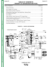
E-5 E-5
THEORY OF OPERATION
POWER WAVE 455/R
Return to Section TOC Return to Section TOC Return to Section TOC Return to Section TOC
Return to Master TOC Return to Master TOC Return to Master TOC Return to Master TOC
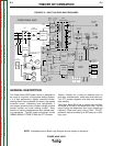
NOTE: Unshaded areas of Block Logic Diagram are the subject of discussion.
+
+
INPUT
BOARD
RECONNECT
SWITCH
LEFT
SWITCH
BOARD
RIGHT
SWITCH
BOARD
INPUT
RECTIFIER
CR1
GATEWAY
BOARD
DC
BUS
BOARD
FEED
HEAD
BOARD
POWER
BOARD
CONTROL
BOARD
STT CHOPPER
BOARD
OUTPUT
CHOKE
STT
ELECTRODE
TERMINAL
ELECTRODE
TERMINAL
THERMOSTATS
T1
T2
AUX
RECONNECT
RELAY
WATER
COOLER
115 VAC
RECP.
115 VAC
FAN
ARC LINK
WIRE
FEEDER
RECP.
S1
S6
CONNECTION
TO WIRE
DRIVE
S1
S6
VOLT
SENSE
BOARD
MAIN
TRANSFORMER
S5
CONTACTOR AND PRECHARGE
CONTROL SIGNALS FROM
CONTROL BOARD
FROM CONTROL
BOARD
2
4
V
A
C
115 VAC
52 VAC
230 VAC
40 VDC
40 VDC
40 VDC
+20 VDC
TO
CHOPPER
BOARD
40 VDC
ARC LINK
CONNECTION
TO
ROBOT
VOLTAGE SENSE
OUTPUT
+20 VDC FROM
POWER BOARD
CT CURRENT
TO CONTROL
BOARD
CAP. V/F
FEEDBACK
CAP. V/F
FEEDBACK
IGBT DRIVE
FROM
CONTROL
BOARD
CT CURRENT
TO CONTROL
BOARD
-15 V
+15 V
+5 V
+5 V ARC LINK
+5V RS232
+15V SPI
STATUS THERMAL
LIGHT LIGHT
S2 WORK
SENSE
LEFT S.B.
CAP. V/F
RIGHT S.B.
CAP. V/F
S3
RS232
LEFT CT
CURRENT
FB
C
U
R
R
E
N
T
F
B
S
T
T
F
B
STT
DRIVE
ARC LINK
IGBT
DRIVES
TO
LEFT
S.B.
TO
RIGHT
S.B.
67A
67B
SW1
BUS BOARD
RECTIFIER
CURRENT
TRANSDUCER
CURRENT
TRANSDUCER
OUTPUT DIODES
D1 -D4
115 VAC
40 VDC
DEVICE NET
VOLTAGE SENSE SELECT
IGBT DRIVE
FROM
CONTROL
BOARD
+5V SPI
RIGHT CT
CURRENT
FB
TO FAN RELAY
CONTACTOR AND
PRECHARGE
CONTROL SIGNALS
65 VDC
WORK
TERMINAL
POWER WAVE 455/R
FIGURE E-4 – DC BUS BOARD, POWER BOARD, FEED HEAD BOARD,
GATEWAY BOARD AND VOLTAGE SENSE BOARD