


TROUBLESHOOTING & REPAIR
F-31 F-31
POWER WAVE 455/R
Return to Section TOC Return to Section TOC Return to Section TOC Return to Section TOC
Return to Master TOC Return to Master TOC Return to Master TOC Return to Master TOC
J7
9 10 11 12 13 14 15 16
1 2 3 4 5 6 7 8
J7
4W 4R
J43
7 8 9 10 11 12
J43
1 2 3 4 5 6
346
345
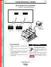
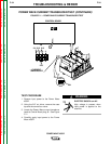
STT OUTPUT
TERMINAL
POWER WAVE
+ OUTPUT
TERMINAL
CONTROL PC BOARD POWER PC BOARD
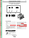
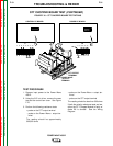
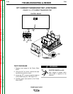
FIGURE F.10 – STT CHOPPER BOARD TEST DETAILS
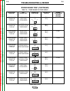
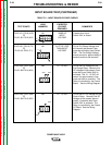
STT CHOPPER BOARD TEST (CONTINUED)
TEST PROCEDURE
1. Remove input power to the Power Wave
455/R.
2. Using the 3/8” nut driver, remove the case
top and the control box cover. See Figure
F.10.
3. Perform the following resistance tests:
+ probe on the STT output terminal
- probe on the Power Wave + output ter-
minal
The reading should be approximately
300,000 ohms
+ probe on the Power Wave + output ter-
minal
- probe on the STT output terminal
The reading should be less than 500 ohms
If both the polarity resistance tests are low,
either the STT Chopper Module is faulty or
diode D6 is shorted. See the Wiring
Diagram.