


TROUBLESHOOTING & REPAIR
F-68 F-68
POWER WAVE 455/R
Return to Section TOC Return to Section TOC Return to Section TOC Return to Section TOC
Return to Master TOC Return to Master TOC Return to Master TOC Return to Master TOC
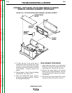
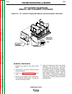
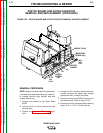
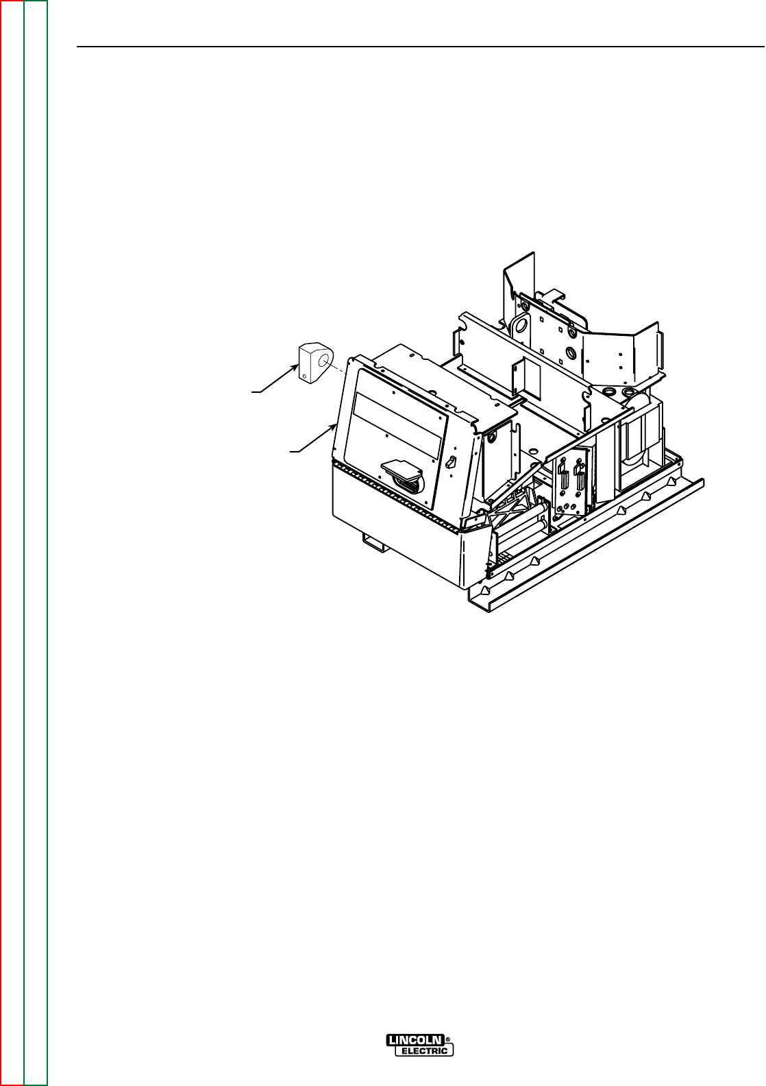
CURRENT
TRANSDUCER
HEAVY LEAD
BOLTED CONNECTION
(BEHIND CASE FRONT)
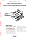
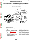
FIGURE F.26 – POWER WAVE CURRENT TRANSDUCER REMOVAL AND REPLACEMENT PROCEDURE
POWER WAVE CURRENT TRANSDUCER
REMOVAL AND REPLACEMENT (CONTINUED)
REMOVAL PROCEDURE
1. Remove input power to the Power Wave
455/R.
2. Using the 3/8” nut driver, remove the case
top and sides and the control box cover.
3. Perform the Capacitor Discharge proce-
dure.
4. Using the 3/8” socket wrench or nut driver,
remove the three screws along the bottom
case front. See Figure F.26.
5. Using the 3/8” socket wrench, remove the
four screws that hold the case front to the
machine.
6. Label all leads to all output terminals. Using
the 5/16” wrench and the 3/4” wrench,
remove all leads from the three output termi-
nals. See the Wiring Diagram.
7. Cut any necessary cable ties. Then careful-
ly swing the front panel aside.
8. Remove the insulating tape from the heavy
lead bolted connection. See Figure F.26.
Using the 9/16” wrenches, remove the bolt,
lock washer and nut.