


TROUBLESHOOTING & REPAIR
F-10 F-10
POWER WAVE 455/R
Return to Section TOC Return to Section TOC Return to Section TOC Return to Section TOC
Return to Master TOC Return to Master TOC Return to Master TOC Return to Master TOC
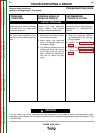
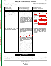
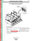
SWITCH
BOARD
CAPACITOR
TERMINALS
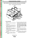
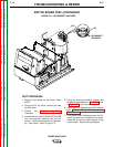
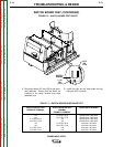
FIGURE F.1 – CAPACITOR DISCHARGE PROCEDURE
INPUT FILTER CAPACITOR DISCHARGE PROCEDURE (CONTINUED)
TEST PROCEDURE
1. Remove input power to the Power Wave
455/R.
2. Using the 3/8” nut driver, remove the left and
right case sides.
3. Be careful not to make contact with the
capacitor terminals that are located in the
bottom center of the left and right side switch
boards. See Figure F.1.
4. Carefully check for a DC voltage at the
capacitor terminals on both boards. Note
the polarity is marked on the PC board and
also lead #19 is positive.
5. If any voltage is present, proceed to Step #6.
If no voltage is present, the capacitors are
discharged.
NOTE: Normally the capacitors discharge in
about two minutes after input power is
removed.
6. Using the high wattage resistor (25-1000
ohms @ 25 watts (minimum), electrically
insulated gloves and pliers, connect the
resistor across the two capacitor terminals.
Hold the resistor in place for 10 seconds.
DO NOT TOUCH THE CAPACITOR TERMI-
NALS WITH YOUR BARE HANDS. NEVER
USE A SHORTING STRAP FOR THIS
PROCEDURE.
7. Repeat procedure for the other capacitor.
8. Recheck the voltage across the capacitor
terminals. The voltage should be zero. If
any voltage remains, repeat the discharge
procedure.
NOTE: If the capacitor voltage is present after
the discharge has been performed, this
may indicate a faulty switch board.