


TROUBLESHOOTING & REPAIR
F-69 F-69
POWER WAVE 455/R
Return to Section TOC Return to Section TOC Return to Section TOC Return to Section TOC
Return to Master TOC Return to Master TOC Return to Master TOC Return to Master TOC
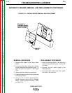
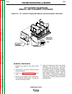
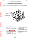
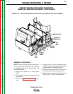
POWER WAVE CURRENT TRANSDUCER
REMOVAL AND REPLACEMENT (CONTINUED)
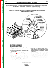
9. Using the phillips head screw driver,
remove the screws and lock washers that
hold the transducer to the front panel.
10. Remove the Power Wave current trans-
ducer.
11. Remove the standoffs from the transducer
and save them for reassembly with the
new transducer.
REPLACEMENT PROCEDURE
1. Attach the standoffs to the transducer.
2. Position the transducer on the back of the
front panel and attach it with the two
phillips screws and lock washers. Feed the
output leads through the transducer.
3. Run the heavy lead through transducer
and secure the bolted connection with the
9/16” bolt, lock washer and nut. Replace
the insulating tape around the connection.
4. Using the 5/16” wrench and the 3/4” wrench,
attach all leads to the three output terminals.
See the Wiring Diagram.
5. Replace all cable ties cut during removal.
6. Install the case top and sides using the 3/8”
nut driver.