


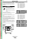
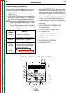

CASE FRONT CONTROLS
All operator controls and adjustments are located on
the case front of the Power Wave. (See Figure B.1)
1. POWER SWITCH: Controls input power to the
Power Wave.
2. STATUS LIGHT: A two color light that indicates sys-
tem errors. Normal operation is a steady green
light. Error conditions are indicated, per Table B.1.
NOTE: The robotic Power Waves’ status light will flash
green, and sometimes red and green, for up to
one minute when the machine is first turned on.
This is a normal situation as the machine goes
through a self test at power up.
TABLE B.1
Light
Meaning
Condition
Steady System OK. Power source
Green communicating normally with
wire feeder and its components.
Blinking Normal for first 1-10 seconds
Green after power is turned on.
Alternating Non-recoverable system fault.
Green Must turn power source off, find
and Red source of error, and turn power
back on to reset. See
Troubleshooting Guide.
Steady See Troubleshooting Guide.
Red
3. HIGH TEMPERATURE LIGHT (thermal overload):
A yellow light that comes on when an over tem-
perature situation occurs. Output is disabled until
the machine cools down. When cool, the light
goes out and output is enabled.
4. 10 AMP WIRE FEEDER CIRCUIT BREAKER:
Protects 40 volt DC wire feeder power supply.
5. 10 AMP AUXILIARY POWER CIRCUIT BREAKER:
Protects 115 volt AC case front receptacle auxil-
iary supply.
6. LEAD CONNECTOR S2 (SENSE LEAD)
7. 5-PIN ARC LINK S1
8. 5-PIN DEVICENET CONNECTOR S5
9. I / O CONNECTOR
10. NEGATIVE OUTPUT TERMINAL
11. INTERFACE CONNECTOR S6
12. STT TERMINAL
13. POSITIVE OUTPUT TERMINAL
14. AUXILIARY OUTPUT
B-6 B-6
OPERATION
POWER WAVE 455/R
Return to Section TOC Return to Section TOC Return to Section TOC Return to Section TOC
Return to Master TOC Return to Master TOC Return to Master TOC Return to Master TOC
POWERWAVE 455/R
I ON
O OFF
FIGURE B.1 – POWER WAVE CASE FRONT CONTROLS
1
11
12
13
2 3
4145
6
7
8
9
10