


WORK VOLTAGE SENSING
The Power Wave is shipped from the factory with the
work sense lead enabled.
For processes requiring work voltage sensing, connect
the (21) work voltage sense lead from the Power Wave
to the work. Attach the sense lead to the work as close
to the weld as practical. To enable the work voltage
sensing in the Power Wave, refer to the section DIP
SWITCH SETTINGS AND LOCATIONS.
ELECTRODE VOLTAGE SENSING
Enabling or disabling electrode voltage sensing is auto-
matically configured through software. Electrode sense
lead 67 must be connected at the wire feeder.
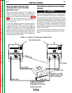
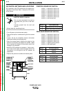
POWER WAVE / POWER FEED WIRE
FEEDER INTERCONNECTIONS
Connect the control cable between the power source
and wire feeder. The wire feeder connection on the
robotic Power Wave is located under the spring loaded
output cover, near the bottom of the case front. The
control cable is keyed and polarized to prevent improp-
er connection.
For convenience sake, the electrode and control
cables can be routed behind the left or right strain
reliefs (under the spring loaded output cover), and
along the channels formed into the base of the Power
Wave, out the back of the channels, and then to the
wire feeder.
Output connections on some Power Waves are made
via 1/2-13 threaded output terminals located beneath
the spring-loaded output cover at the bottom of the
case front. On machines which carry the CE mark, out-
put connections are made via Twist-Mate receptacles,
also located beneath the spring-loaded output cover at
the bottom of the case front.
A work lead must be run from the negative (-) power
source output connection to the work piece. The work
piece connection must be firm and secure, especially if
pulse welding is planned.
Excessive voltage drops at the work piece connection
often result in unsatisfactory pulse welding perfor-
mance.
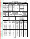
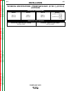
CONTROL CABLE SPECIFICATIONS
It is recommended that genuine Lincoln control cables
be used at all times. Lincoln cables are specifically
designed for the communication and power needs of
the Power Wave / Power Feed system.
The use of non-standard cables, especially in lengths
greater than 25 feet, can lead to communication prob-
lems (system shutdowns), poor motor acceleration
(poor arc starting) and low wire driving force (wire feed-
ing problems).
Lincoln control cables are copper 22 conductor cable in
a SO-type rubber jacket.
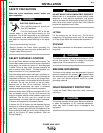
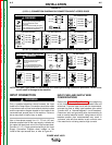
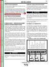
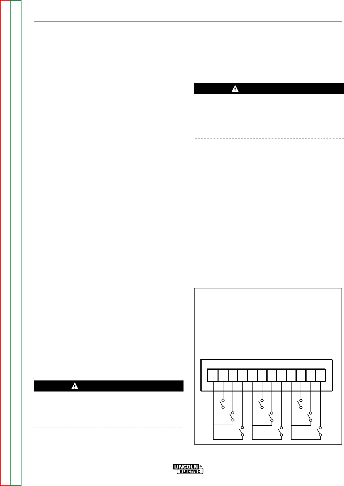
EXTERNAL I/O CONNECTOR
The Power Wave is equipped with a port for making sim-
ple input signal connections. The port is divided into
three groups: Trigger group, Cold Inch Group and
Shutdown Group. Because the Power Wave is a “slave”
on the DeviceNet network, the Trigger and Cold Inch
Groups are disabled when the DeviceNet/Gateway is
active.
The Shutdown Group is always enabled. Shutdown 2 is
used for signaling low flow in the water cooler. Unused
shutdowns must be jumpered. Machines from the fac-
tory come with the shutdowns already jumpered. (See
Figure A.4)
A-9 A-9
INSTALLATION
POWER WAVE 455/R
Return to Section TOC Return to Section TOC Return to Section TOC Return to Section TOC
Return to Master TOC Return to Master TOC Return to Master TOC Return to Master TOC
CAUTION
CAUTION
D
E
F
1
2
3
4
5
6
78
910
11
12
G
H
I
A
B
C
+15 VDC for Trigger Group
Trigger Input
Dual Procedure Input
4 Step Input
+15 VDC for Cold Inch Group
Cold Inch Forward
Cold Inch Reverse
Gas Purge Input
+15 for shutdown group
Shutdown1 input
Shutdown2 input
Reserved for future use
FIGURE A.4 – INPUT PORT CONNECTIONS