


TROUBLESHOOTING & REPAIR
F-16 F-16
POWER WAVE 455/R
Return to Section TOC Return to Section TOC Return to Section TOC Return to Section TOC
Return to Master TOC Return to Master TOC Return to Master TOC Return to Master TOC
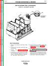
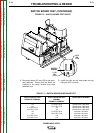
INPUT RECTIFIER TEST (CONTINUED)
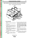
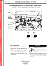
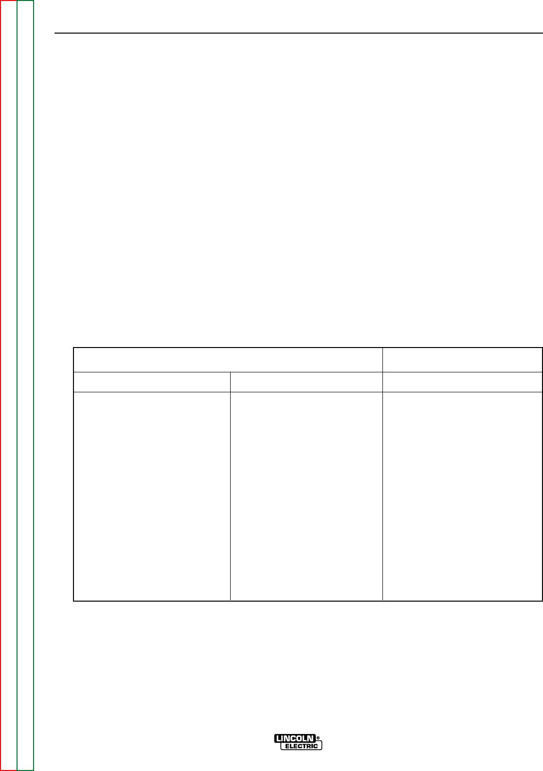
6. Use the analog ohmmeter to perform the
tests detailed in Table F.2.
7. If the input rectifier does not meet the
acceptable readings outlined in the table,
the component may be faulty. Replace.
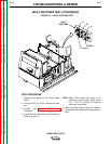
NOTE: Before replacing the input rectifier, per-
form the Switch Board Test and the
Input Contactor Test.
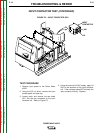
8. When installing a new input rectifier, see
Input Rectifier Removal and
Replacement procedure.
9. If the input rectifier is good, be sure to
reconnect the positive and negative leads
to the correct terminals and torque to 31
in.-lbs. See the Wiring Diagram.
10. Replace any RTV sealant previously
removed.
11. Install the case top.
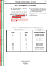
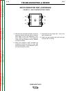
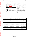
TEST POINT TERMINALS
A
B
C
A
B
C
NEG
NEG
NEG
POS
POS
POS
NEG
NEG
NEG
POS
POS
POS
A
B
C
A
B
C
Greater than 1000 ohms
Greater than 1000 ohms
Greater than 1000 ohms
Approx. 500 ohms
Approx. 500 ohms
Approx. 500 ohms
Approx. 500 ohms
Approx. 500 ohms
Approx. 500 ohms
Greater than 1000 ohms
Greater than 1000 ohms
Greater than 1000 ohms
TABLE F.2 – INPUT RECTIFIER TEST POINTS AND ACCEPTABLE READINGS
ANALOG METER X100
RANGE
Acceptable Meter Readings
+ Probe - Probe