


TROUBLESHOOTING & REPAIR
F-13 F-13
POWER WAVE 455/R
Return to Section TOC Return to Section TOC Return to Section TOC Return to Section TOC
Return to Master TOC Return to Master TOC Return to Master TOC Return to Master TOC
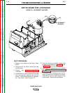
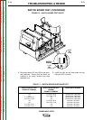
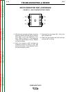
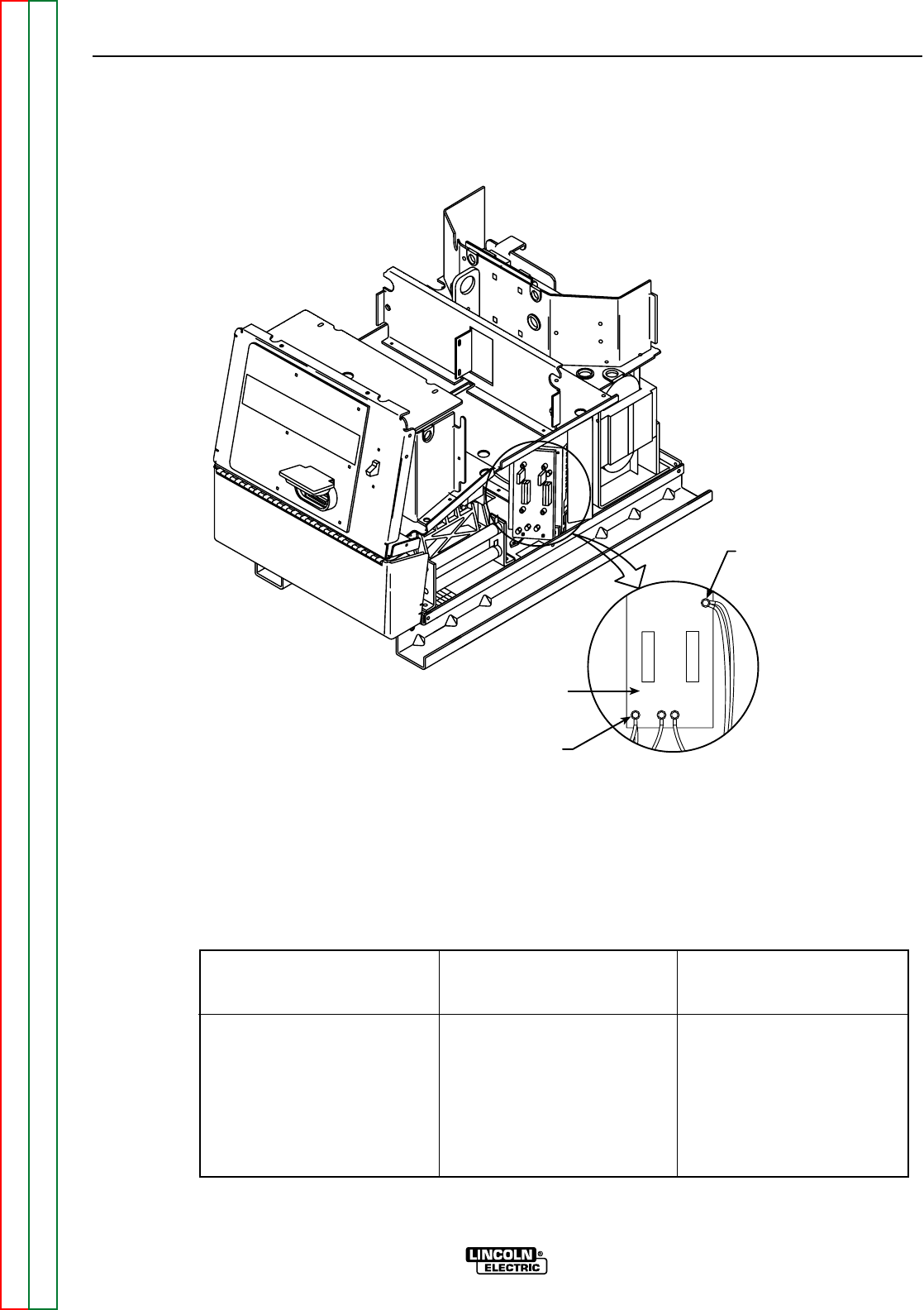
SWITCH
BOARD
11/12
OR
15/16
13/14
OR
17/18
-20 +19
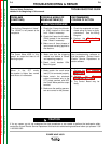
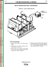
FIGURE F.3 – SWITCH BOARD TEST POINTS
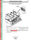
SWITCH BOARD TEST (CONTINUED)
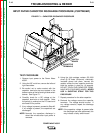
8. Reconnect leads 19C and 19D to the recon-
nect switches. Ensure that the leads are
installed in the same location they were
removed from.
9. Install the right and left case sides and top
using the 3/8” nut driver.
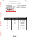
APPLY POSITIVE TEST
PROBE TO TERMINAL
APPLY NEGATIVE TEST
NORMAL
PROBE TO TERMINAL
RESISTANCE READING
TABLE F.1 – SWITCH BOARD RESISTANCE TEST
+19
+19
11/12 OR 15/16
13/14 OR 17/18
- 20
- 20
11/12 OR 15/16
13/14 OR 17/18
11/12 OR 15/16
13/14 OR 17/18
- 20
- 20
11/12 OR 15/16
13/14 OR 17/18
+19
+19
Greater than 1000 ohms
Greater than 1000 ohms
Greater than 1000 ohms
Greater than 1000 ohms
Less than 100 ohms
Less than 100 ohms
Less than 100 ohms
Less than 100 ohms