


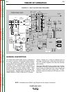
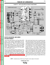
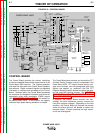
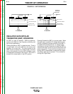

CONTROL BOARD
The Control Board performs the primary interfacing
functions to establish and maintain output control of the
Power Wave 455R machine. The function generator
and weld files exist within the Control Board hardware
and software. Digital command signals and feedback
information is received and processed at the Control
Board. Software within the Control Board processes
the command and feedback information and sends the
appropriate pulse width modulation (PWM) signals
(see PULSE WIDTH MODULATION in this section) to
the switch board IGBTs. In this manner, the digitally
controlled high-speed welding waveform is created.
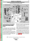
The Control Board also monitors and controls the STT
(Surface Tension Transfer) circuitry incorporated in the
Power Wave 455R. STT output currents and arc volt-
ages are monitored, and the appropriated gate firing
signals are applied (or removed) from the STT
Chopper Board and switch boards to create a low spat-
ter, low fume MIG welding process. See GENERAL
DESCRIPTION OF STT (SURFACE TENSION
TRANSFER PROCESS) in this section.
In addition, the Control Board monitors the ther-
mostats, the main transformer primary currents and
input filter capacitor voltages. Depending on the fault
condition, the Control Board will activate the thermal
and/or the status light and will disable or reduce the
machine output. In some conditions the input contac-
tor will be de-energized.
E-7 E-7
THEORY OF OPERATION
POWER WAVE 455/R
Return to Section TOC Return to Section TOC Return to Section TOC Return to Section TOC
Return to Master TOC Return to Master TOC Return to Master TOC Return to Master TOC
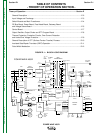
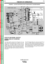
FIGURE E.6 – CONTROL BOARD
+
+
INPUT
BOARD
RECONNECT
SWITCH
LEFT
SWITCH
BOARD
RIGHT
SWITCH
BOARD
INPUT
RECTIFIER
CR1
GATEWAY
BOARD
DC
BUS
BOARD
FEED
HEAD
BOARD
POWER
BOARD
CONTROL
BOARD
STT CHOPPER
BOARD
OUTPUT
CHOKE
STT
ELECTRODE
TERMINAL
ELECTRODE
TERMINAL
THERMOSTATS
T1
T2
AUX
RECONNECT
RELAY
WATER
COOLER
115 VAC
RECP.
115 VAC
FAN
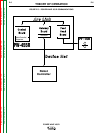
ARC LINK
WIRE
FEEDER
RECP.
S1
S6
CONNECTION
TO WIRE
DRIVE
S1
S6
VOLT
SENSE
BOARD
MAIN
TRANSFORMER
S5
CONTACTOR AND PRECHARGE
CONTROL SIGNALS FROM
CONTROL BOARD
FROM CONTROL
BOARD
2
4
V
A
C
115 VAC
52 VAC
230 VAC
40 VDC
40 VDC
40 VDC
+20 VDC
TO
CHOPPER
BOARD
40 VDC
ARC LINK
CONNECTION
TO
ROBOT
VOLTAGE SENSE
OUTPUT
+20 VDC FROM
POWER BOARD
CT CURRENT
TO CONTROL
BOARD
CAP. V/F
FEEDBACK
CAP. V/F
FEEDBACK
IGBT DRIVE
FROM
CONTROL
BOARD
CT CURRENT
TO CONTROL
BOARD
-15 V
+15 V
+5 V
+5 V ARC LINK
+5V RS232
+15V SPI
STATUS THERMAL
LIGHT LIGHT
S2 WORK
SENSE
LEFT S.B.
CAP. V/F
RIGHT S.B.
CAP. V/F
S3
RS232
LEFT CT
CURRENT
FB
C
U
R
R
E
N
T
F
B
S
T
T
F
B
STT
DRIVE
ARC LINK
IGBT
DRIVES
TO
LEFT
S.B.
TO
RIGHT
S.B.
67A
67B
SW1
BUS BOARD
RECTIFIER
CURRENT
TRANSDUCER
CURRENT
TRANSDUCER
OUTPUT DIODES
D1 -D4
115 VAC
40 VDC
DEVICE NET
VOLTAGE SENSE SELECT
IGBT DRIVE
FROM
CONTROL
BOARD
+5V SPI
RIGHT CT
CURRENT
FB
TO FAN RELAY
CONTACTOR AND
PRECHARGE
CONTROL SIGNALS
65 VDC
WORK
TERMINAL
POWER WAVE 455/R