


TROUBLESHOOTING & REPAIR
F-22 F-22
POWER WAVE 455/R
Return to Section TOC Return to Section TOC Return to Section TOC Return to Section TOC
Return to Master TOC Return to Master TOC Return to Master TOC Return to Master TOC
DC BUS POWER SUPPLY PC BOARD TEST(CONTINUED)
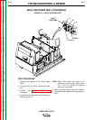
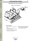
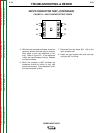
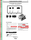
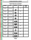
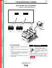
6. Check the DC Bus Power Supply PC Board
input and output voltages according to Table
F.3. See Figure F.7 and the Wiring
Diagram.
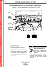
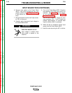
ELECTRIC SHOCK can kill.
High voltage is present at the
terminals of Capacitor C3 near
where testing is to be done.
7. If all the voltages are correct, the DC Bus
Power Supply PC Board is operating prop-
erly.
8. If any of the output voltages are not cor-
rect and the input voltage is correct, the
DC Bus Power Supply PC Board may be
faulty.
9. If the input voltage is not correct, check
the leads between the DC Bus Power
Supply PC Board and the Power PC
Board Rectifier. See the Wiring Diagram.
10. When finished testing, replace the case
top.
WARNING
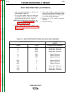
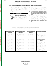
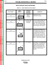
Plug P46 – Pin 1
Plug P47 – Pin 7
Plug P47 – Pin 8
Plug P47 – Pin 4
Plug P47 – Pin 3
Plug P46 – Pin 3
Plug P47 – Pin 6
Plug P47 – Pin 6
Plug P47 – Pin 2
Plug P47 – Pin 1
65 – 75 VDC
38.0 – 42.0 VDC
38.0 – 42.0 VDC
38.0 – 42.0 VDC
38.0 – 42.0 VDC
Should be same as the
Power PC Board
Rectifier
Supply to Power PC
Board
Supply to Power PC
Board
Supply to Feed Head PC
Board
Supply to S1 Wire
Feeder Receptacle
Positive Meter Probe
Test Point
Negative Meter Probe
Test Point
Approximate Voltage
Reading
Conditions/Comments
TABLE F.3 – DC BUS POWER SUPPLY PC BOARD VOLTAGE TABLE