


TROUBLESHOOTING & REPAIR
F-36 F-36
POWER WAVE 455/R
Return to Section TOC Return to Section TOC Return to Section TOC Return to Section TOC
Return to Master TOC Return to Master TOC Return to Master TOC Return to Master TOC
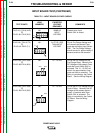
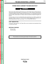
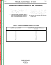
TABLE F.6 - CURRENT FEEDBACK AT VARIOUS OUTPUT LOADS
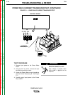
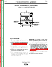
POWER WAVE CURRENT TRANSDUCER TEST (CONTINUED)
8. If for any reason the machine cannot be
loaded to 250 amps, Table F.6 shows what
feedback voltage is produced at various cur-
rent loads.
9. If the correct supply voltages are applied to
the current transducer, and with the machine
loaded, the feedback voltage is missing or
not correct, the current transducer may be
faulty. Also make certain that lead 211
(plug J8 pin 1) has continuity (zero ohms)
between the current transducer and the
control board. See the Wiring Diagram.
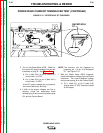
10. Install the right side case cover using the
3/8” nut driver.
OUTPUT LOAD CURRENT
500
450
400
350
300
250
200
150
100
50
EXPECTED TRANSDUCER FEEDBACK
VOLTAGE
4.0
3.6
3.2
2.8
2.4
2.0
1.6
1.2
0.8
0.4