


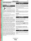
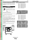

DIP SWITCH SETTINGS AND LOCATIONS
DIP switches on the PC boards allow for custom con-
figuration of the Power Wave. Access the DIP switch-
es as follows:
ELECTRIC SHOCK CAN KILL.
• Do not touch electrically live parts or
electrodes with your skin or wet cloth-
ing.
• Insulate yourself from the work and
ground.
• Always wear dry insulating gloves.
• Turn off power at the disconnect switch.
• Remove the top four screws securing the front access
panel.
• Loosen, but do not completely remove, the bottom
two screws holding the access panel.
• Open the access panel, allowing the weight of the
panel to be carried by the bottom two screws. Make
sure to prevent the weight of the access panel from
hanging on the harness.
• Adjust the DIP switches as necessary. Using a pen-
cil or other small object, slide the switch left for the
ON position or to the right for the OFF position, as
appropriate.
• Replace the panel and screws and restore power.
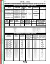
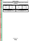
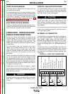
CONTROL BOARD DIP SWITCH:
switch 1 = reserved for future use
switch 2 = reserved for future use
switch 3 = reserved for future use
switch 4 = reserved for future use
switch 5 = reserved for future use
switch 6 = reserved for future use
switch 7 = reserved for future use
switch 8 = work sense lead
switch 8 work sense lead
off work sense lead not connected
on work sense lead connected
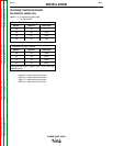
FEED HEAD BOARD DIP SWITCH:
switch 1 = reserved for future use
switch 2 = reserved for future use
switch 3 = reserved for future use
switch 4 = reserved for future use
switch 5 = reserved for future use
switch 6 = reserved for future use
switch 7 = negative polarity switch
switch 8 = high speed gear
switch 7 electrode polarity
off positive
on negative
switch 8 wire drive gear
off low speed gear
on high speed gear
A-10 A-10
INSTALLATION
POWER WAVE 455/R
Return to Section TOC Return to Section TOC Return to Section TOC Return to Section TOC
Return to Master TOC Return to Master TOC Return to Master TOC Return to Master TOC
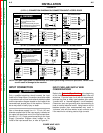
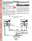
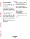
CONTROL BOARD
(LOCATED IN
CONTROL BOX
BEHIND CASE
FRONT)
FEED HEAD
BOARD
(LOCATED IN
CONTROL
BOX BEHIND
CASE FRONT)
BANK S1
BANK S2
RIGHT
LEFT
DEVICENET/
GATEWAY
BOARD
(LOCATED
BEHIND
FRONT
COVER)
FRONT
COVER
CASE FRONT
OPENING IN
CASE FRONT
TO ACCESS
CONTROL
BOX
WARNING