


TROUBLESHOOTING & REPAIR
F-15 F-15
POWER WAVE 455/R
Return to Section TOC Return to Section TOC Return to Section TOC Return to Section TOC
Return to Master TOC Return to Master TOC Return to Master TOC Return to Master TOC
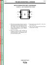
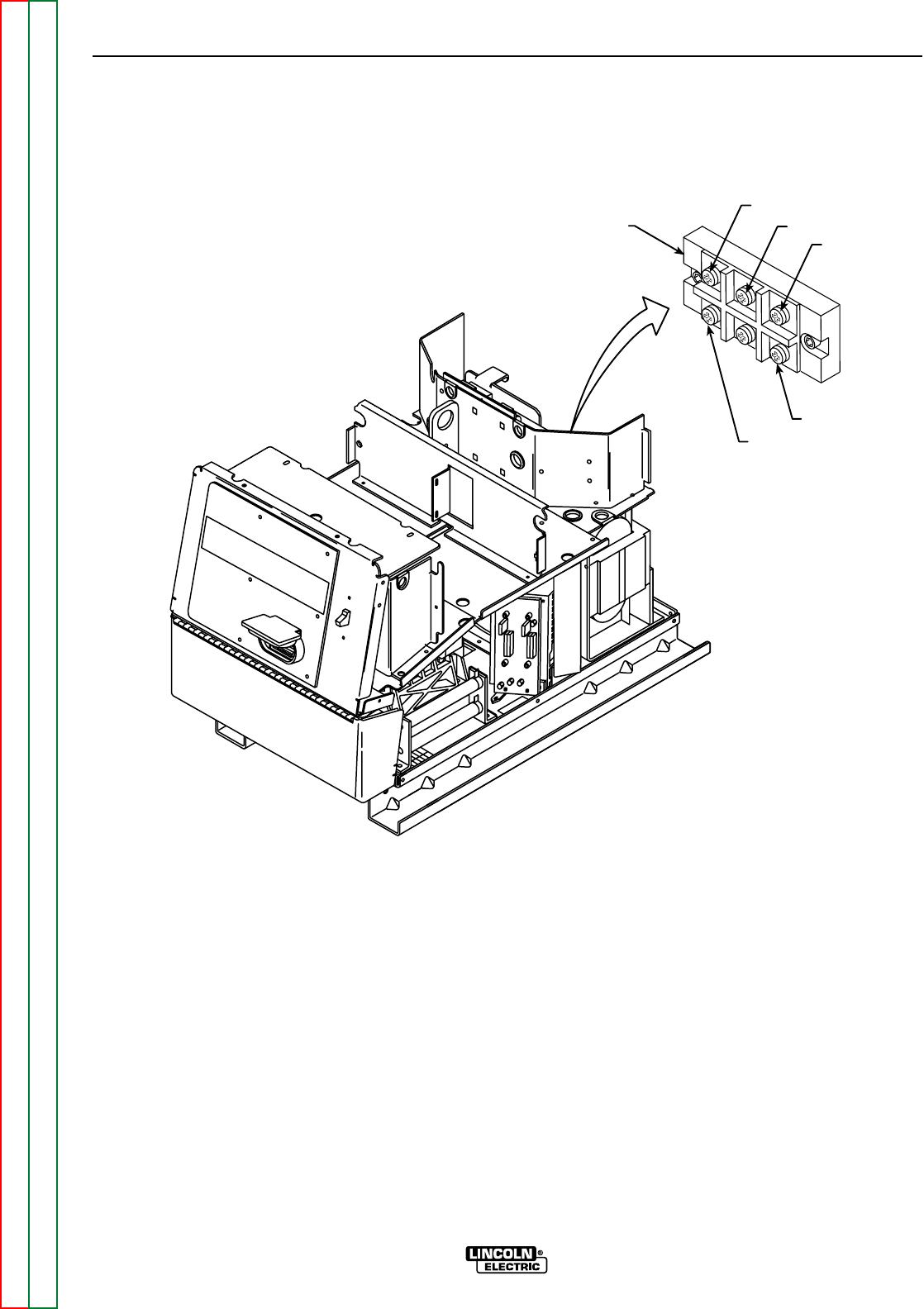
NEG (-)
POS (+)
A
B
C
INPUT
RECTIFIER
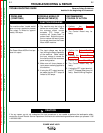
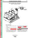
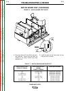
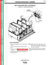
FIGURE F.4 – INPUT RECTIFIER TEST
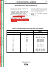
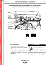
INPUT RECTIFIER TEST (CONTINUED)
TEST PROCEDURE
1. Remove input power to the Power Wave
455/R.
2. Using the 3/8” nut driver, remove the case
top.
3. Perform the Capacitor Discharge
Procedure.
4. Locate the Input Rectifier and lead locations.
Refer to Figure F.4.
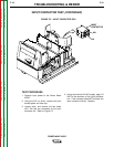
NOTE: Some RTV sealant may have to be
removed from the input rectifier termi-
nals. The RTV should be replaced
when test is complete.
5. With the phillips head screw driver remove
the positive and negative leads from the rec-
tifier.