


Troubleshooting & Repair ...................................................................................................Section F
How to Use Troubleshooting Guide ...........................................................................................F-2
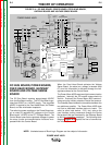
PC Board Troubleshooting Procedures.......................................................................................F-3
Troubleshooting Guide ................................................................................................................F-4
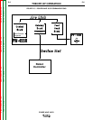
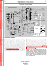
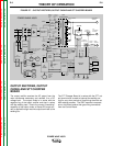
Test Procedures ..........................................................................................................................F-9
Input Filter Capacitor Discharge Procedure .........................................................................F-9
Switch Board Test ...............................................................................................................F-11
Input Rectifier Test .............................................................................................................F-14
Input Contactor Test............................................................................................................F-17
DC Bus Power Supply PC Board Test................................................................................F-20
Power Board Test ..............................................................................................................F-23
Input Board Test .................................................................................................................F-26
STT Chopper Board Test ....................................................................................................F-30
Power Wave Current Transducer Test ...............................................................................F-33
STT Current Transducer Test ............................................................................................F-37
Output Rectifier Test ..........................................................................................................F-41
Auxiliary Transformer No. 1 Test .......................................................................................F-43
Auxiliary Transformer No. 2 Test .......................................................................................F-46
Component Removal and Replacement Procedure..................................................................F-48
Input Rectifier Removal and Replacement ........................................................................F-48
Input Contactor Removal and Replacement ......................................................................F-50
Auxiliary Transformer No. 1 Removal and Replacement Procedure..................................F-52
Auxiliary Transformer No. 2 Removal and Replacement Procedure..................................F-55
Control, Feed Head, or Voltage Sense PC Board Removal and Replacement .................F-58
Gateway PC Board Removal and Replacement ...............................................................F-62
STT Current Transducer Removal and Replacement ...................................................... F-64
Power Wave Current Transducer Removal and Replacement.......................................... F-67
Output Rectifier, STT Chopper Board and Rectifier Module Removal
and Replacement ........................................................................................................F-70
Switch Board and Filter Capacitor Removal and Replacement .........................................F-74
Retest after Repair ...................................................................................................................F-77
Section F-1 Section F-1
TABLE OF CONTENTS
- TROUBLESHOOTING & REPAIR SECTION -
POWER WAVE 455/R
Return to Master TOC Return to Master TOC Return to Master TOC Return to Master TOC