


TROUBLESHOOTING & REPAIR
F-51 F-51
POWER WAVE 455/R
Return to Section TOC Return to Section TOC Return to Section TOC Return to Section TOC
Return to Master TOC Return to Master TOC Return to Master TOC Return to Master TOC
INPUT
CONTACTOR
601
X4
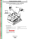
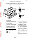
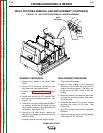
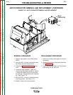
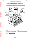
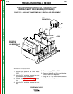
FIGURE F.19 – INPUT CONTACTOR REMOVAL AND REPLACEMENT
INPUT CONTACTOR REMOVAL AND REPLACEMENT (CONTINUED)
REMOVAL PROCEDURE
1. Remove input power to the Power Wave
455/R.
2. Using the 3/8” nut driver, remove the case
top, sides, and input access panel.
3. Perform the Capacitor Discharge proce-
dure
4. Locate the input contactor. Label and,
using the phillips head screwdriver, careful-
ly remove the leads from the input contac-
tor terminals. Note placement for reassem-
bly. See Figure F.19.
5. With the 5/16” nut driver, remove the three
mounting screws. See Figure F.19.
6. Carefully remove the input contactor.
REPLACEMENT PROCEDURE
1. Mount the contactor and tighten the mount-
ing screws.
2. Assemble the leads to the correct terminals.
See Figure F.18.
3. Install the case top, sides, and input access
panel using the 3/8” nut driver.