


TROUBLESHOOTING & REPAIR
F-71 F-71
POWER WAVE 455/R
Return to Section TOC Return to Section TOC Return to Section TOC Return to Section TOC
Return to Master TOC Return to Master TOC Return to Master TOC Return to Master TOC
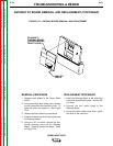
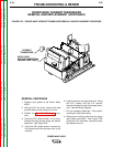
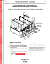
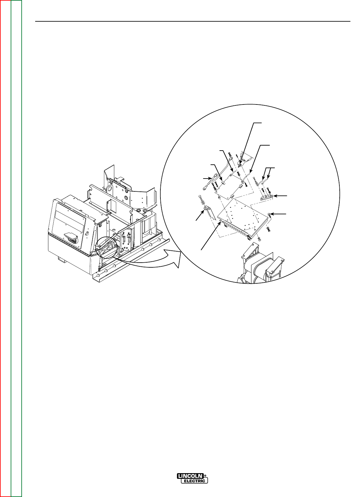
TRANSFORMER
LEADS
RECTIFIER
MODULE
POSITIVE
OUTPUT
LEAD
HEATSINK
MOUNT
BOLTS (4X)
RECTIFIER
THERMOSTAT
(LEADS 291 & 292)
HEATSINK
STT LEAD
LEAD 287
(SNUBBER
DIODE)
PLUG J10
LEAD 289B
(STT SNUBBER
CAPACITOR)
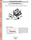
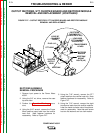
FIGURE F.27 – OUTPUT RECTIFIER, STT CHOPPER BOARD AND RECTIFIER MODULE
REMOVAL AND REPLACEMENT
OUTPUT RECTIFIER, STT CHOPPER BOARD AND RECTIFIER MODULE
REMOVAL AND REPLACEMENT (CONTINUED)
RECTIFIER ASSEMBLY
REMOVAL PROCEDURE
1. Remove input power to the Power Wave
455/R.
2. Using the 3/8” nut driver, remove the case
top and sides.
3. Perform the Capacitor Discharge proce-
dure.
4. Using the 9/16” wrench, remove the Power
Wave positive output lead from the rectifier
heat sink. Note fastener hardware for
reassembly. Refer to Figure F.27.
5. Using the 7/16” wrench, remove the STT
output lead from the rectifier heat sink. Note
fastener hardware for reassembly. Refer to
Figure F.27.
6. Using the 7/16” wrench, remove the eight
transformer leads from the rectifier modules.
Label the leads and take note of lead place-
ment for reassembly. Note that each screw
has two flat washers and one lock washer.