


TROUBLESHOOTING & REPAIR
F-47 F-47
POWER WAVE 455/R
Return to Section TOC Return to Section TOC Return to Section TOC Return to Section TOC
Return to Master TOC Return to Master TOC Return to Master TOC Return to Master TOC
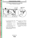
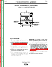
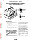
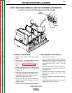
P50
P52
4 5 6
3 4
1 2 3
1 2
H4 H3 H1
H5 H6 H2
33A
350
352
VIEWED FROM
TRANSFORMER
LEAD END
VIEWED FROM
TRANSFORMER
LEAD SIDE
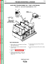
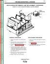
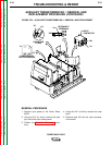
FIGURE F.17 – AUXILIARY TRANSFORMER NO. 2 TEST
AUXILIARY TRANSFORMER NO. 2 TEST (CONTINUED)
TEST PROCEDURE
1. Remove the main input power to the Power
Wave 455/R machine.
2. Remove any load that may be connected to
the 115 VAC receptacle.
3. Using the 3/8” nut driver, remove the case
top.
4. Locate plugs P52 and P50 at the Auxiliary
Transformer No. 2. Refer to Figure F.17.
5. Carefully apply the correct input power.
ELECTRIC SHOCK can kill.
High voltage is present at both
plugs.
6. Check for 115 VAC at plug P52 pins 1 and
4 (leads 350 to 33A). Check for 230 VAC
at plug P52 pins 1 and 2 (leads 350 to
352).
7. If 115 VAC and 230 VAC are present,
Auxiliary Transformer No. 2 is good.
8. If 115 is not present between pins 1 and 4,
and 230 VAC is not present between pins 1
and 2, check the associated leads and
plugs for loose or faulty connections.
9. Carefully test for the correct AC input volt-
age applied to the primary windings at plug
P50. See the Wiring Diagram.
10. If the correct AC input voltage is applied to
the primary of the Auxiliary Transformer
No. 2 and the secondary voltage is NOT
correct, the transformer may be faulty.
Replace.
11. Replace any cables ties and insulation
removed earlier.
12. Install the case top using the 3/8” nut dri-
WARNING