


TROUBLESHOOTING & REPAIR
F-42 F-42
POWER WAVE 455/R
Return to Section TOC Return to Section TOC Return to Section TOC Return to Section TOC
Return to Master TOC Return to Master TOC Return to Master TOC Return to Master TOC
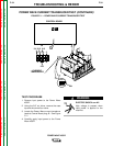
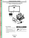
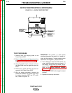
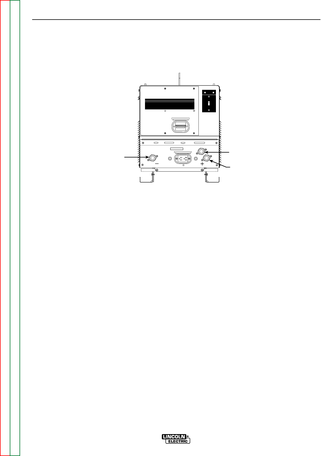
STT OUTPUT
TERMINAL
POSITIVE (+)
OUTPUT
TERMINAL
NEGATIVE (-)
OUTPUT
TERMINAL
POWERWAVE 455/R
I ON
O OFF
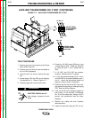
FIGURE F.15 – OUTPUT RECTIFIER TEST
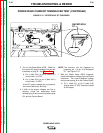
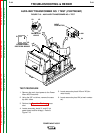
OUTPUT RECTIFIER TEST (CONTINUED)
TEST PROCEDURE
1. Remove main input supply power to the
Power Wave 455/R.
2. Remove the case top and sides and perform
the Input Filter Capacitor Discharge pro-
cedure.
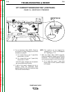
3. Using the 5/16” wrench, remove and insu-
late lead 202A from the negative output ter-
minal.
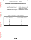
4. Remove any output load that may be con-
nected to the Power Wave 455/R.
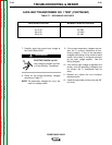
5. With the analog ohmmeter, measure the
resistance between the positive and nega-
tive output terminals (NOT the STT termi-
nal). Refer to Figure F.15.
IMPORTANT: The positive (+) meter probe
must be attached to the positive (+) output ter-
minal and the negative (-) meter probe must be
attached to the negative (-) output terminal.
6. If the reading is more than 200 ohms, the
output rectifier modules are not shorted. If
the reading is less than 200 ohms, one or
more of the rectifier modules are shorted.
Refer to the Output Rectifier Module
Replacement procedure.
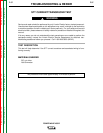
7. Reconnect lead 202A to the negative output
terminal.
8. Replace the case top and sides.