


Chapter 3 System Controller Alphabetical Command Reference 91
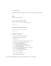
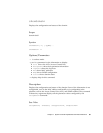
See Also
enablecomponent, disablecomponent, and the “Disable Component” section
of the “Troubleshooting” chapter in the Sun Fire 6800/4810/4800/3800 Systems
Platform Administration Manual for a step-by-step procedure on displaying a
component.
Examples
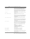
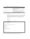
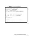
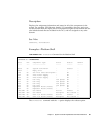
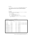
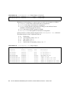
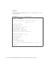
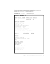
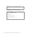
CODE EXAMPLE 3-50 shows sample output for the showcomponent sb4 command.
The abbreviations for the Component field are:
■ Nx Node name
■ SBx CPU/Memory board, where x is 0 – 5
■ Px Port, where x is 0 – 3
■ Bx Physical memory bank, where x is 0 – 1
■ Lx Logical memory bank, where x is 0 – 3. There are two DIMMs per
logical memory bank.
CODE EXAMPLE 3-50 showcomponent sb4 Sample Output
schostname:SC> showcomponent sb4
Component Status Pending POST Description
-------- ------ ------- ---- -----------
/NO/SB4/P0 enabled - pass UltraSPARC III+,750Mhz, 8M ECache
/NO/SB4/P1 enabled - pass UltraSPARC III+,750Mhz, 8M ECache
/NO/SB4/P2 enabled - pass UltraSPARC III+,750Mhz, 8M ECache
/NO/SB4/P3 enabled - pass UltraSPARC III+,750Mhz, 8M ECache
/NO/SB4/P0/B0/L0 enabled - pass 256M DRAM
/NO/SB4/P0/B0/L2 enabled - pass 256M DRAM
/NO/SB4/P0/B1/L1 enabled - pass 256M DRAM
/NO/SB4/P0/B1/L3 enabled - pass 256M DRAM
/NO/SB4/P1/B0/L0 enabled - pass 256M DRAM
/NO/SB4/P1/B0/L2 enabled - pass 256M DRAM
/NO/SB4/P1/B1/L1 enabled - pass 256M DRAM
/NO/SB4/P1/B1/L3 enabled - pass 256M DRAM
/NO/SB4/P2/B0/L0 enabled - pass 256M DRAM
/NO/SB4/P2/B0/L2 enabled - pass 256M DRAM
/NO/SB4/P2/B1/L1 enabled - pass 256M DRAM
/NO/SB4/P2/B1/L3 enabled - pass 256M DRAM
/NO/SB4/P3/B0/L0 enabled - pass 256M DRAM
/NO/SB4/P3/B0/L2 enabled - pass 256M DRAM