


Chapter 2 System Controller Syntax, Arguments, and Device Names 5
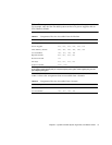
Note – The components in TABLE 2-1 and TABLE 2-2 depend on the system you have.
For example, only the Sun Fire 6800 system can have six power supplies and six
CPU/Memory boards.
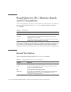
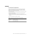
TABLE 2-2 shows the components that are accessible from a domain.
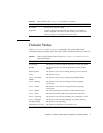
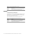
TABLE 2-1 Components That Are Accessible From the Platform
Device Description Device Name
Power grids* GRID0, GRID1
Power supplies PS0, PS1, PS2, PS3, PS4, PS5
CPU/Memory boards SB0, SB1, SB2, SB3, SB4, SB5
I/O assemblies IB6, IB7, IB8, IB9
Repeater boards RP0, RP1, RP2, RP3
ID/Source board ID0
Fan trays FT0, FT1, FT2, FT3
System controller SSC0, SSC1
* Power grids are not a component but a division of the Sun Fire 6800 system into two distinct halves
of the system. Power supplies ps0, ps1, and ps2 comprise power grid 0. Power supplies ps3, ps4, and
ps5 comprise power grid 1.
TABLE 2-2 Components That Are Accessible From a Domain
Device Description Device Name
CPU/Memory boards SB0, SB1, SB2, SB3, SB4, SB5
I/O Assemblies IB6, IB7, IB8, IB9