18 MatrixPRO • 8x8 DVI Router • User’s Guide
2. Hardware Orientation
MatrixPRO 8x8 DVI Router Front Panel
j~íêáñmol=UñU=asf=oçìíÉê=cêçåí=m~åÉä
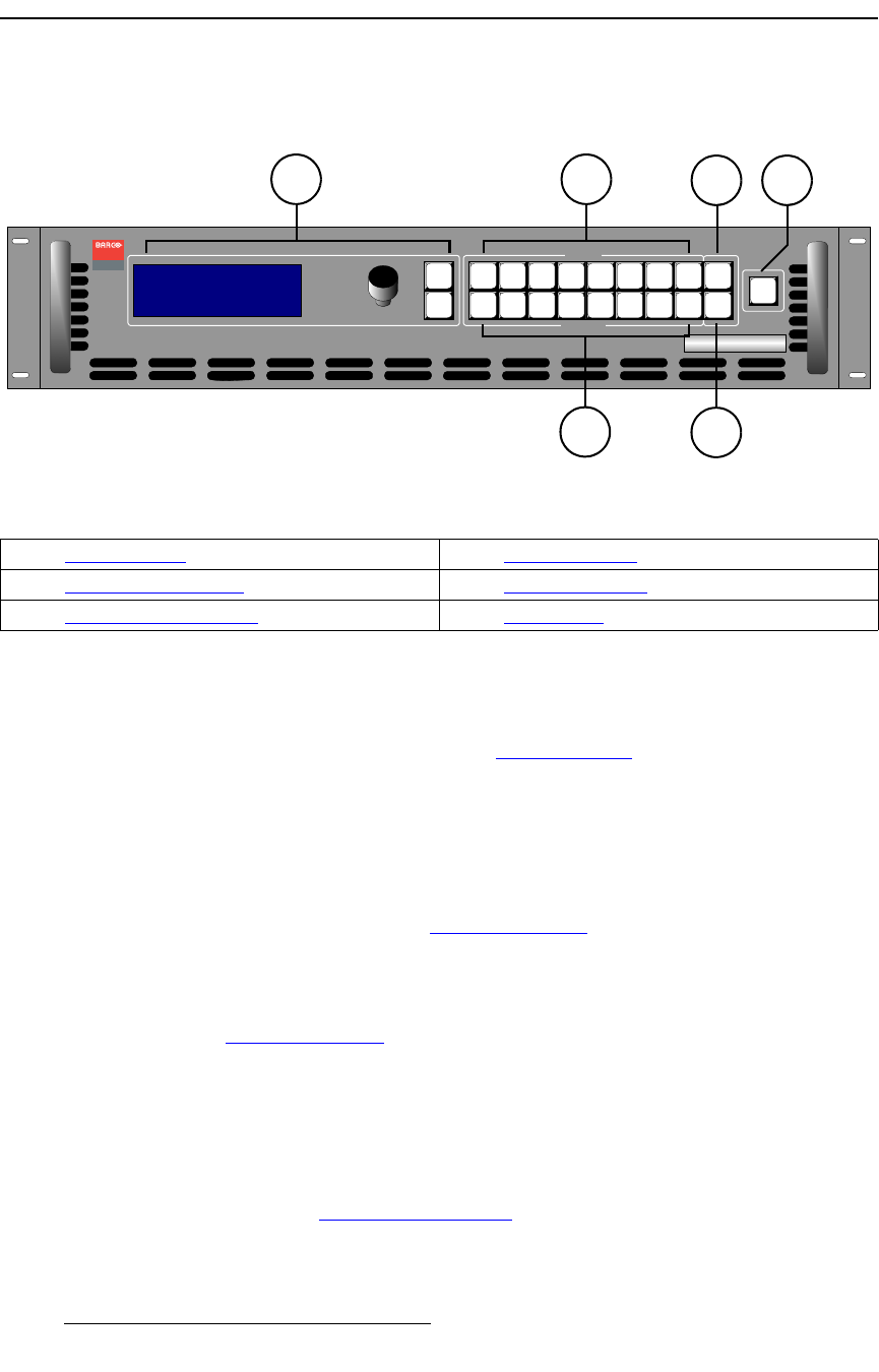
The figure below illustrates the MatrixPRO 8x8 DVI Router front panel:
Figure 2-1. MatrixPRO 8x8 DVI Router Front Panel
Following are descriptions of each front panel control feature:
1) Display Section
The Display Section includes the display, the ADJUST knob and two “menu
navigation” buttons. Refer to the “Display Section” heading on page 20 for
complete details.
2) Input Selection Section
On the top row at the right-side of the front panel, eight input (crosspoint) selection
buttons are provided on the top row. Routing is performed as follows:
~ Select an output, select an input, press TAKE.
In Chapter 4, refer to the “Performing a Take
” section on page 48 for details.
3) Output Selection Section
On the bottom row at the right-side of the front panel, eight output (crosspoint)
selection buttons are provided on the bottom row. In Chapter 4, refer to the
“Performing a Take” section on page 48 for details.
4) TEST PAT Button
The TEST PAT button functions as a ninth input, enabling you to route a selected
test pattern to one or more outputs. When pressed, the button lights and the
system pends the test pattern route. Test patterns are pre-selected using the Test
Pattern Menu. Patterns include H ramp, V ramp, 100% color bars, 75% color
bars, grids, burst, grey field, white field, black field, and grey steps. In Chapter 4,
refer to the “Routing a Test Pattern
” section on page 50 for details.
Visibly yours
SEL
ESC
ADJUST
TM
MatrixPRO
MP 8x8 DVI
>Setup
Status
EDID Setup
>>
>>
>>
TAKE
OUTPUT
INPUT
1
1
2
2
3
3
4
4
5
5
6
6
7
7
8
8
TEST
PAT
RGB
MUTE
21
4
5
3
6
1) Display Section 4) TEST PAT Button
2) Input Selection Section 5) RGB MUTE Button
3) Output Selection Section 6) TAKE Button


