


MatrixPRO • 8x8 DVI Router • User’s Guide 21
2. Hardware Orientation
MatrixPRO 8x8 DVI Router Rear Panel
j~íêáñmol=UñU=asf=oçìíÉê=oÉ~ê=m~åÉä
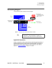
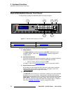
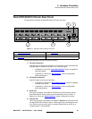
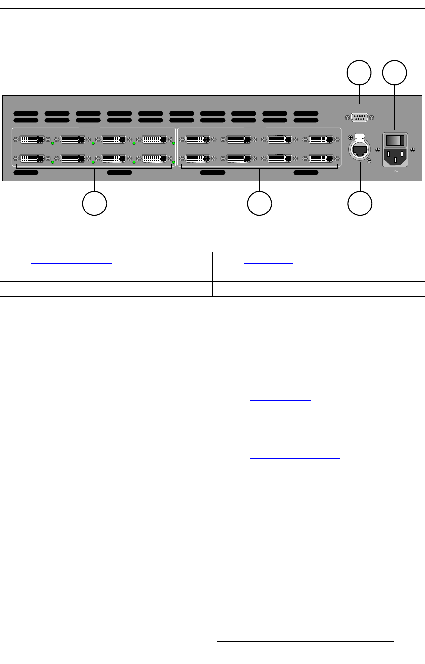
The figure below illustrates the MatrixPRO 8x8 DVI Router rear panel:
Figure 2-1. MatrixPRO 8x8 DVI Router Rear Panel
Following are descriptions of each rear panel connector:
1) DVI Input Connectors
Eight DVI input connectors are provided. Each connector has an associated LED
that lights green to indicate the presence of a valid video signal.
~ In Appendix A, refer to the “Input Specifications” section on page 86 for
input video details.
~ In Appendix A, refer to the “DVI Connector” section on page 88 for
pinout specifications.
2) DVI Output Connectors
Eight DVI output connectors are provided.
~ In Appendix A, refer to the “Output Specifications” section on page 86
for output video details.
~ In Appendix A, refer to the “DVI Connector” section on page 88 for
pinout specifications.
3) Serial Port
One 9-pin D connector is provided for RS-232 serial communications with the
MatrixPRO 8x8 DVI Router chassis and for downloading code in the field. In
Appendix A, refer to the “Serial Connector
” section on page 90 for pinouts.
4) Ethernet Port
One RJ-45 connector is provided for 10/100BaseT Ethernet communications with
the MatrixPRO 8x8 DVI Router chassis. When (optionally) connecting the router
to an Encore or remote control panel, a standard Ethernet hub or switch on an
isolated network is recommended.
INPUTS
SERIAL
ETHERNET
5
1
6
2
7
3
8
4
OUTPUTS
5
1
6
2
7
3
8
4
100-240 V 50-60 Hz
3.0 A
4
3
1
5
2
1) DVI Input Connectors 4) Ethernet Port
2) DVI Output Connectors 5) AC Connector
3) Serial Port