


88 MatrixPRO • 8x8 DVI Router • User’s Guide
^K==péÉÅáÑáÅ~íáçåë
Pinouts
máåçìíë=
The following topics are discussed in this section:
• DVI Connector
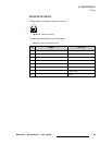
• Ethernet Connector
• Serial Connector
asf=`çååÉÅíçê
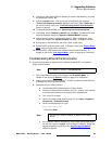
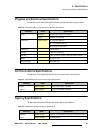
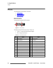
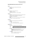
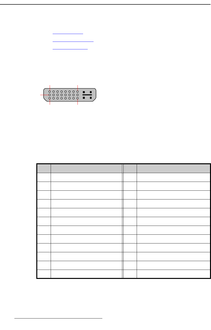
The figure below illustrates the DVI connector:
Figure A-1. DVI Connector
The table below lists DVI Connector pinouts. Please note:
• T.M.D.S = Transition Minimized Differential Signal
• DDC = Display Data Channel
Table A-6. DVI Connector Pinouts
Pin Signal Pin Signal
1 T.M.D.S. Data 2- 13 T.M.D.S. Data 3+
2 T.M.D.S. Data 2+ 14 +5V Power
3 T.M.D.S. Data 2/4 Shield 15 ground (for +5V)
4 T.M.D.S. Data 4- 16 Hot Plug Detect
5 T.M.D.S. Data 4+ 17 T.M.D.S. Data 0-
6 DDC Clock 18 T.M.D.S. Data 0+
7 DDC Data 19 T.M.D.S. Data 0/5 Shield
8 Analog Vertical Sync 20 T.M.D.S. Data 5-
9 T.M.D.S. Data 1- 21 T.M.D.S. Data 5+
10 T.M.D.S. Data 1+ 22 T.M.D.S. Clock Shield
11 T.M.D.S. Data 1/3 Shield 23 T.M.D.S. Clock +
12 T.M.D.S. Data 3- 24 T.M.D.S. Clock -
1 8
9
17 24