


A-6
Cisco Application Deployment Engine (ADE) 2130 and 2140 Series Appliance Hardware Installation Guide
78-18579-02
Appendix A Troubleshooting
Reading the LEDs
NIC LEDs
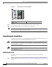
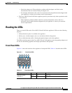
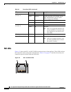
Figure A-2 shows the NIC 1 and NIC 2 LEDs located on the rear of the appliance. These LEDs indicate
the connection activity and speed of the NIC ports. Table A-2 on page A-7 describes the activity and
connection speed associated with each LED state.
Figure A-2 NIC 1 and NIC 2 LEDs
Appliance Status
(location 2)
Green On Standby or ready for operation
Green Blinking Degraded operation (for example, power
supply nonredundancy, part of system
memory mapped out of BIOS)
Amber On One or more critical fault conditions
Amber Blinking One or more noncritical fault conditions
Hard Disk Drive
(location 3)
Green On HDD activity
Amber On HDD fault
Note This is an aggregated indication for
all hard disk drives. Each hard disk
drive contains its own activity and
fault LEDs.
NICs (location 4) Green On NIC activity
System ID (location 5) Blue System identity
Note LED can be toggled remotely or by
the front-panel ID switch to obtain
the system’s identity.
Table A-1 Front-Panel LEDs (continued)
LED Color State Description
231350
1 2