


1-7
Cisco Application Deployment Engine (ADE) 2130 and 2140 Series Appliance Hardware Installation Guide
78-18579-02
Chapter 1 Introducing the Cisco Application Deployment Engine 2130 and 2140 Series Appliance
Hardware Features
Front Control Panel LEDs and Switches
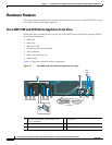
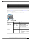
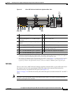
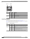
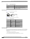
Figure 1-4 shows the location of the Cisco ADE 2130 and 2140 Series appliance LEDs and switches on
the front panel. Table 1-4 describes the LEDs located on the front panel. Table 1-5 on page 1-8 describes
the switches located on the front panel.
Figure 1-4 Cisco ADE 2130 and 2140 Series Appliance Front Control Panel
4 Control switches and status LEDs (see
Figure 1-4)
11 Hard drive fault LED (one per drive)
5 Hard drive 0 12 Hard drive activity LED (one per drive)
6 Hard drive 2 13 Serial number of ADE 1010/2120
7 Hard drive 4 14 Product ID (PID) of ADE 1010/2120
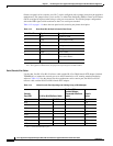
Table 1-4 Front Control Panel LEDs
LED Color State Description
Appliance Power
(location 1)
Green On Power on
Off Off Power off
Appliance Status
(location 2)
Green On Standby or ready for operation
Green Blinking Degraded operation (for example, power
supply nonredundancy, part of system
memory mapped out of BIOS)
Amber On One or more critical fault conditions
Amber Blinking One or more noncritical fault conditions
Hard Disk Drive
(location 3)
Green On HDD activity
Amber On HDD fault
Note This is an aggregated indication for
all hard disk drives. Each hard disk
drive contains its own activity and
fault LEDs.
A
B C
D
E
H
F
I
G
1 2 3 4 5
6
7
8
9
231190