


1-8
Cisco Application Deployment Engine (ADE) 2130 and 2140 Series Appliance Hardware Installation Guide
78-18579-02
Chapter 1 Introducing the Cisco Application Deployment Engine 2130 and 2140 Series Appliance
Hardware Features
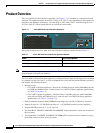
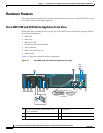
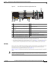
Cisco ADE 2130 and 2140 Series Appliance Rear View
On the rear panel, viewing from left to right, the Cisco ADE 2130 and 2140 Series appliance includes
the following components:
• Two PS/2 connectors (mouse and keyboard)
• One RJ-45 serial (console) connector
• Two RJ-45 NIC (1 and 2) ports
• One video (VGA) port
• Two USB 2.0 ports
• Five PCI adapter card slots (expansion slots)
• (Optional) Two RJ-45 NIC (3 and 4) ports
Note If the optional NIC ports (3 and 4) using a mezzanine module are not installed, a filler panel
occupies this space.
• AC power connector or DC power connector
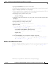
Figure 1-5 shows the orientation of the following components.
Note The locations of the rack-mounting brackets are also shown on the left and right sides of the appliance.
(See the “Rack-Mounting Configuration Guidelines” section on page 3-2 for instructions on how to
install the mounting brackets.)
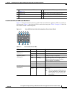
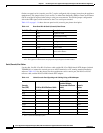
NICs (location 4) Green On NIC activity
System ID (location 5) Blue System identity
Note LED can be toggled remotely or by
the front-panel ID switch to obtain
the system’s identity.
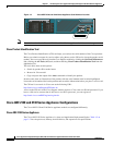
Table 1-5 Front Control Panel Switches
Switch Description
ID (location 6) Toggles appliance ID LED
NMI (location 7) Asserts the NMI
1
(non-maskable interrupt) to the processor on the
appliance
1. When pressed, clears the processor allowing the processor to continue to execute the software normally.
Reset (location 8) Resets the appliance
Power (location 9) Toggles the appliance power
Table 1-4 Front Control Panel LEDs
LED Color State Description