


1-14
Cisco Application Deployment Engine (ADE) 2130 and 2140 Series Appliance Hardware Installation Guide
78-18579-02
Chapter 1 Introducing the Cisco Application Deployment Engine 2130 and 2140 Series Appliance
Hardware Features
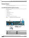
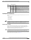
On the rear-panel serial (console) port, Pin 7 can be configured with a jumper located on the appliance
motherboard. This jumper allows you to set Pin 7 to either Data Set Ready (DSR) or Data Carrier Detect
(DCD) as might be required when using a serial port concentrator. The default jumper configuration
selects the DSR signal, which conforms to the Cisco serial port standard.
Table 1-12 on page 1-14 shows the rear-panel serial (console) port pinout description.
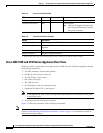
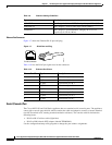
Serial (Console) Port Cables
Use the thin, flat, RJ-45-to-RJ-45 rollover cable and the RJ-45-to-DB-9 female DTE adapter (labeled
TERMINAL) to connect the console port to an ASCII terminal or a PC running terminal-emulation
software. Table 1-13 lists the pinouts for the asynchronous serial console port, the RJ-45-to-RJ-45
rollover cable, and the RJ-45-to-DB-9 female DTE adapter.
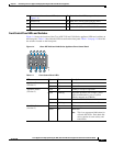
Table 1-12 Rear-Panel RJ-45 Serial (Console) Port Pinout
Serial Port Pin Signal Description
1 RTS Request to send
2 DTR Data terminal ready
3 TXD Transmit data
4 GND Earth ground
5 GND Earth ground
6 RXD Receive data
7DSR or DCD
1
1. A jumper block on the appliance motherboard determines whether DSR or DCD is routed to
Pin 7. The appliance motherboard has the jumper block preconfigured with DSR enabled.
Data set ready or
Data carrier detect
8CTSClear to send
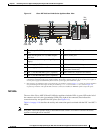
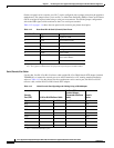
Table 1-13 Serial Console Port Signaling and Cabling Using a DB-9 Adapter
Console
Port (DTE) RJ-45-to-RJ-45 Rollover Cable
RJ-45-to-DB-9
Terminal Adapter
(Connected to Rollover
Cable)
Console
Device
Signal RJ-45 Pin RJ-45 Pin DB-9 Pin Signal
RTS 1
1
1. Pin 1 is connected internally to pin 8.
88 CTS
DTR 2 7 6 DSR
TXD 3 6 2 RXD
GND 4 5 5 GND
GND 5 4 5 GND
RXD 6 3 3 TXD
DSR 7 2 4 DTR
CTS 8
1
17 RTS