


3-21
Cisco Application Deployment Engine (ADE) 2130 and 2140 Series Appliance Hardware Installation Guide
78-18579-02
Chapter 3 Installing the Cisco ADE 2130 and 2140 Series Appliance
Powering Up the Cisco ADE 2130 and 2140 Series Appliance
Power-Up Procedure (DC Power Supply)
To power up a Cisco ADE 2130 and 2140 Series appliance with a DC power supply and verify its
initialization and self-test, follow this procedure. When the procedure is finished, the appliance is ready
to configure.
If a redundant power supply is used, separate DC power sources are needed for each power supply. This
allows you to turn off power for one power supply without affecting the power source for the other.
Step 1 Review the information in the “Safety Guidelines” section on page 2-2.
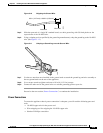
Step 2 Plug the Molex terminal block connector into the power connector located on the rear right-hand side of
the appliance. (See location 1 in Figure 1-5 on page 1-9.)
Step 3 Connect the DC power input wires to the DC power source at your installation site.
Step 4 Press the power button on the front of the appliance. (See location 9 in Figure 3-13 on page 3-21.)
The appliance should begin its powerup procedure.
Step 5 After the operating system boots up, observe the front-panel LEDs to verify that your system is operating
properly. (See Figure 3-13 on page 3-21 and the “Checking the LEDs” section on page 3-21.)
Once the operating system boots, you are ready to initialize the basic software configuration. (See the
software installation guide or user guide that shipped with your appliance, for proper configuration
procedures.)
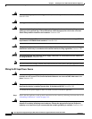
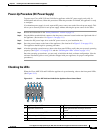
Checking the LEDs
When the Cisco ADE 2130 and 2140 Series appliance is up and running, observe the front-panel LEDs.
(See Figure 3-13.)
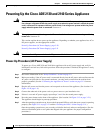
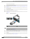
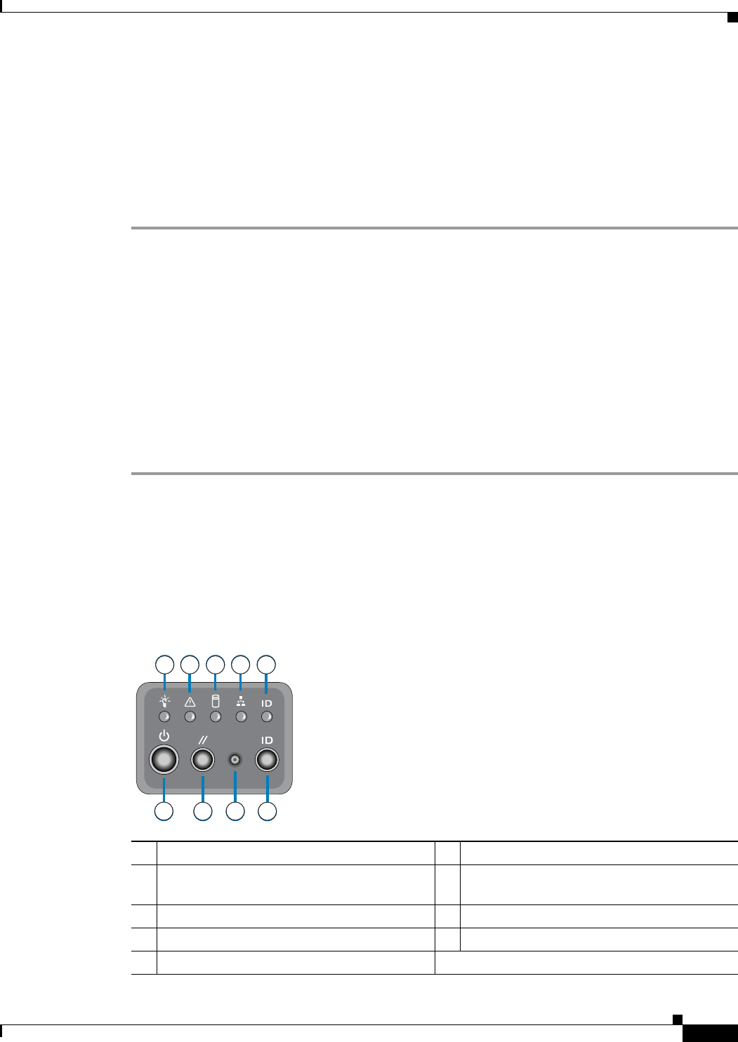
Figure 3-13 Cisco ADE 2130 and 2140 Series Appliance Front Control Panel
1 Appliance power LED 6 ID control switch (push button)
2 Appliance status LED 7 NMI (nonmaskable interrupt) recessed
button
1
3 Hard disk drive activity LED 8 Reset push button
4 NIC activity (all NICs) 9 Appliance power push button
5 Appliance system ID LED
A
B C
D
E
H
F
I
G
1 2 3 4 5
6
7
8
9
231190