


1-13
Cisco Application Deployment Engine (ADE) 2130 and 2140 Series Appliance Hardware Installation Guide
78-18579-02
Chapter 1 Introducing the Cisco Application Deployment Engine 2130 and 2140 Series Appliance
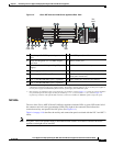
Hardware Features
Note The configuration/setup utility program is located in the Cisco ADE 2130 and 2140 Series appliance
ROM and can be accessed through the serial (console) port.
Serial (Console) Port Connector
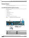
The Cisco ADE 2130 and 2140 Series appliance has an RJ-45 serial port connector located on the back
of the appliance. This connector is shared with the RJ-45 serial port connector located on the front panel.
Note When one RJ-45 serial port connector is in use, the other is disabled. For example, if the rear-panel RJ-45
serial port connector is in use, the front-panel RJ-45 serial port connector is disabled and vice versa.
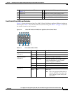
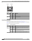
Figure 1-8 shows the pin number assignments for the RJ-45 serial (console) port connector on the back
or front of the appliance. These pin number assignments conform to industry standards.
Figure 1-8 Serial Port Connector
Note The serial (console) RJ-45 port pinout differs slightly between the front- and rear-panel ports,
specifically in relation to Pin 6 and Pin 7.
On the front-panel serial (console) port, Pin 6 is used as a serial port selection input. Grounding the
signal on Pin 6 disables the rear-panel serial (console) port so that the front-panel port is active. This
feature allows you to plug into and use the front-panel port without regard to whether anything is
connected to the rear-panel port.
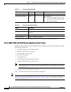
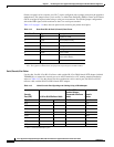
Table 1-11 lists the front-panel serial (console) port pinout descriptions.
210222
8 7 6 5 4 3 2 1
RJ-45 connector
Table 1-11 Front-Panel RJ-45 Serial (Console) Port Pinout
Serial Port Pin Signal Description
1 RTS Request to send
2 DTR Data terminal ready
3 TXD Transmit data
4 GND Earth ground
5 In Use When grounded, indicates that
the port is routed to the
front-panel port.
6 RXD Receive data
7DSRData set ready
8CTSClear to send