


4-10
Cisco Application Deployment Engine (ADE) 2130 and 2140 Series Appliance Hardware Installation Guide
78-18579-02
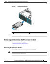
Chapter 4 Installing the Cisco ADE 2130 and 2140 Series Appliance Hardware Options
Installing and Removing Memory
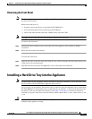
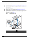
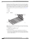
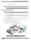
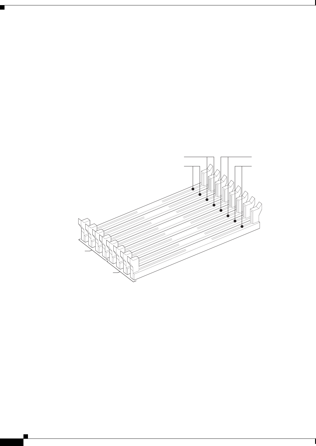
The appliance provides eight DIMM slots across two branches (0 and 1) of four channels, channel A
through Channel D. Channel A consists of DIMM slots A1 and A2, Channel B consists of DIMM slots
B1 and B2, Channel C consists of DIMM slots C1 and C2, and Channel D consists of DIMM slots D1
and D2. The slots associated with each channel, are located next to each other. A diagram on the logic
board near the DIMM slots illustrates the location of the DIMM slots. Each slot accepts 533/667-MHz
stacked Double-Data-Rate 2 (DDR2) Error Correction Code (ECC) or non-ECC unbuffered memory.
DIMMs are populated in pairs and are populated in the following DIMM slot order (see Figure 4-5):
• A1 and B1
• C1 and D1
• A2 and B2
• C2 and D2
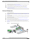
Figure 4-5 DIMM Slots
DIMMs within a given pair must be identical with respect to size, speed, and organization. However,
DIMM capacities can be different between different DIMM pairs. For example, a valid mixed-DIMM
configuration may have:
• 512-MB DIMMs installed in DIMM slots A1 and B1
• 1-GB DIMMs installed in DIMM slots C1 and D1
The following restrictions apply:
• Single-channel mode is supported only with a 512-MB DIMM installed in DIMM slot A1.
• For best performance, the number of DIMMs installed should be balanced across both memory
branches. For example, a four-DIMM configuration performs better than a two-DIMM configuration
and should be installed in DIMM slots A1, B1, C1, and D1. An eight-DIMM configuration performs
better than a six-DIMM configuration.
DIMM D2
DIMM D1
DIMM C2
DIMM C1
DIMM B2
DIMM B1
DIMM A2
DIMM A1
Branch 0
Channel A
Channel B
Channel D
Channel C
Branch 1
231197