


1-10
Cisco Application Deployment Engine (ADE) 2130 and 2140 Series Appliance Hardware Installation Guide
78-18579-02
Chapter 1 Introducing the Cisco Application Deployment Engine 2130 and 2140 Series Appliance
Hardware Features
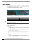
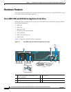
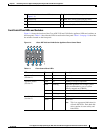
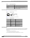
Figure 1-6 NIC LEDs
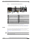
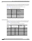
AC and DC Power Supply LEDs
The rear of Cisco ADE 2130 and 2140 Series appliance includes LEDs that indicate the power status of
the AC and DC power supplies. (See locations 4 and 5 in Figure 1-5 on page 1-9.)
Table 1-7 describes the power status associated with the AC power supply LEDs. Table 1-8 describes the
power status associated with the DC power supply LEDs.
Tab le 1- 6 NI C L ED s
LED Color State Description
Left
(location 1)
Off 10-Mb/s connection
Green Solid 100-Mb/s connection
Amber Solid 1000-Mb/s (or 1-Gb/s) connection
Right
(location 2)
Off No network connection
Green Solid Network connection
Green Blinking Transmit/receive activity
231350
1 2
Table 1-7 AC Power Supply LED
LED Color State Description
Below AC
power
supply input
connector
Off No AC input power to power supply
Green Blinking AC power applied to power supply and standby voltages are
available
Green Solid All power available
Amber Blinking AC power supply warning due to overcurrent or
overtemperature condition or slow fan
Amber Solid AC power supply failed or shut down due to blown fuse, high
overcurrent or overtemperature condition, or fan failure