


SPI9000 Inverter Unit FI9 – FI14 User Manual
1-2
For more information visit:
www.EatonElectrical.com
MN04004002E
September 2006
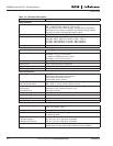
Standard Features of SPI Inverter Units
●
Air cooling
●
Standard board
●
Alphanumeric control panel with fiber connection
●
EMC Class T (EN 61800-3 for IT networks)
●
Safety CE / UL
● External charging required
● I/O Modules A1 and A2
● IP00
Storage
If the inverter is to be stored before use, make sure that the ambient conditions are
acceptable.
Storage temperature: -40 to 158°F (-40 to 70°C)
Relative humidity: <95%, no condensation
If the inverter is stored for over 12 months, contact Eaton before connecting the inverter to
the power supply.
Maintenance
In normal conditions, Cutler-Hammer inverters are maintenance-free. However, we
recommend cleaning the heatsink with compressed air whenever necessary. The cooling fan
can easily be changed if required.
It may also be necessary to check the tightening torques of terminals at certain intervals.
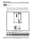
Technical Data
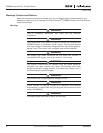
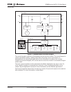
Figure 1-1 presents the block diagram of the SPI9000 inverter. The inverter mechanically
consists of two units, the Power Unit and the Control Unit.
The Power Unit contains an inverter bridge which consists of IGBT switches and produces
symmetrical, three-phase PWM-modulated AC voltage to the motor.
The Motor and Application Control Block is based on microprocessor software. The
microprocessor controls the motor based on the information it receives through
measurements, parameter settings, control I/O and the control keypad. The motor and
application control block control the motor control ASIC which, in turn, calculates the IGBT
positions. Gate drivers amplify these signals for driving the IGBT inverter bridge.