


SPI9000 Inverter Unit FI9 – FI14 User Manual
5-8 For more information visit: www.EatonElectrical.com MN04004002E
September 2006
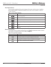
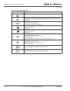
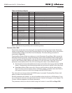
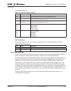
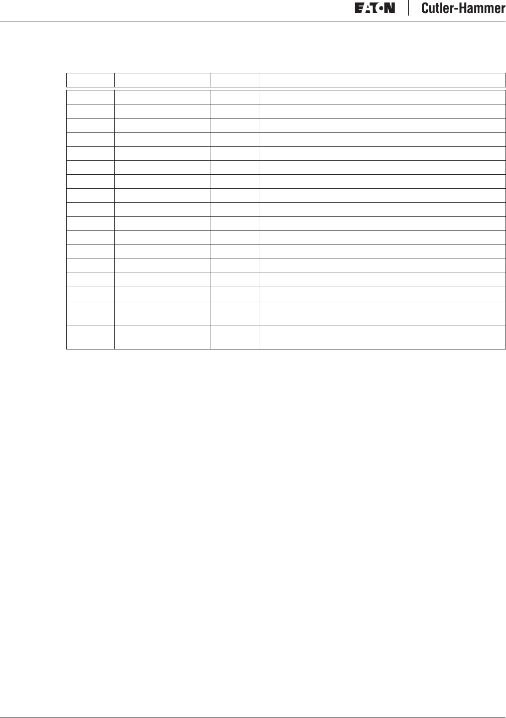
Table 5-6: Monitored Signals
Note: Applications may embody more monitoring values.
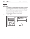
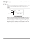
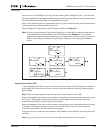
Parameter Menu (M2)
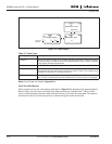
Parameters are the way of conveying the commands of the user to the inverter. Parameter
values can be edited by entering the Parameter Menu from the Main Menu when the location
indication M2 is visible on the first line of the display. The value editing procedure is
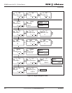
presented in Figure 5-6.
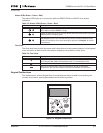
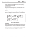
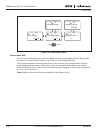
Pressing Menu Button Right once takes you to the Parameter Group Menu (G#). Locate the
desired parameter group by using the Browser buttons and press Menu Button Right again
to see the group and its parameters. Use the Browser buttons to find the parameter (P#) you
want to edit. Pressing Menu Button right takes you to the edit mode. As a sign of this, the
parameter value starts to blink. You can now change the value in two different ways:
● Set the desired value with the Browser buttons and confirm the change with the ENTER
button. Consequently, the blinking stops and the new value is visible in the value field.
● Press Menu Button Right once more. Now you will be able to edit the value digit by
digit. This may come in handy, when a relatively greater or smaller value than that on
the display is desired. Confirm the change with the ENTER button.
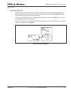
The value will not change unless the ENTER button is pressed. Pressing Menu Button Left
takes you back to the previous menu.
Several parameters are locked, i.e. cannot be edited, when the drive is in RUN status. If you
try to change the value of such a parameter the text *Locked* will appear on the display. The
inverter must be stopped to edit these parameters.
The parameter values can also be locked using the function in menu M6 (see Page 5-22).
Code Signal Name Unit Description
V7.1 Output frequency Hz Frequency to the motor
V7.2 Frequency reference Hz
V7.3 Motor speed rpm Calculated motor speed
V7.4 Motor current A Measured motor current
V7.5 Motor torque % Calculated torque based/nominal torque of the unit
V7.6 Motor power % Calculated actual power/nominal power of the unit
V7.7 Motor voltage V Calculated motor voltage
V7.8 DC-link voltage V Measured DC-link voltage
V7.9 Unit temperature °C Heatsink temperature
V7.10 Motor temperature % Calculated motor temperature
V7.11 Voltage input V AI1
V7.12 Current input mA AI2
V7.13 DIN1, DIN2, DIN3 — Digital input statuses
V7.14 DIN4, DIN5,DIN6 — Digital input statuses
V7.15 DO1, RO2, RO3 — Digital and relay output statuses
V7.16 Analog output
current
mA AO1
M1.17 Multimonitoring
items
Displays three selectable monitoring values. See
Page 5-23.