


SPI9000 Inverter Unit FI9 – FI14 User Manual
MN04004002E
For more information visit: www.EatonElectrical.com 1-3
September 2006
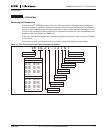
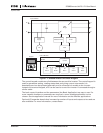
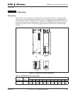
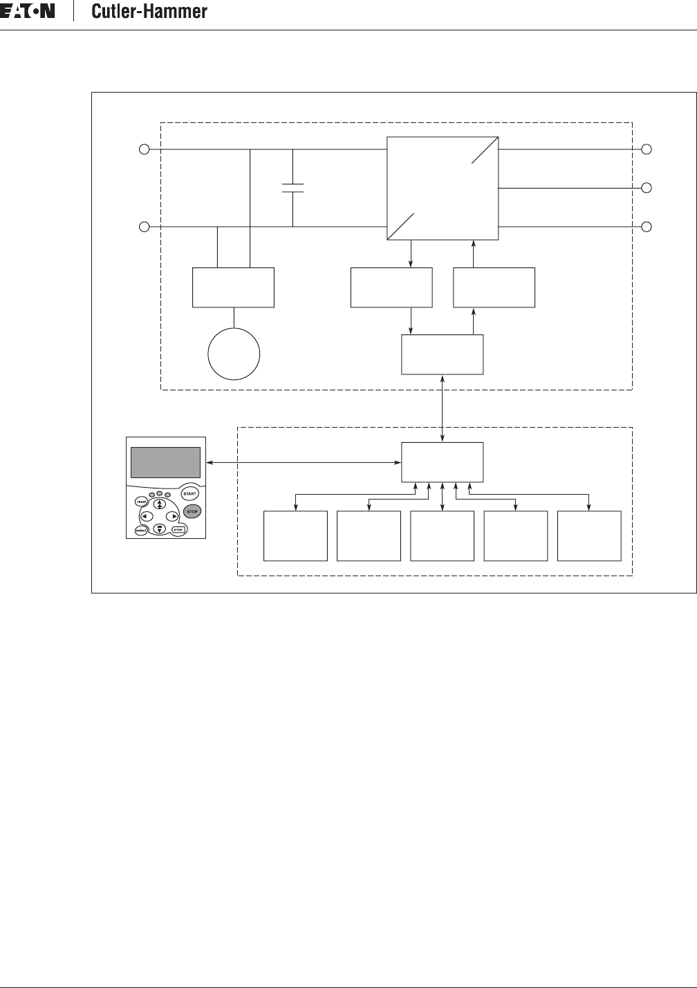
Figure 1-1: SPI9000 Inverter Unit Block Diagram
The control keypad constitutes a link between the user and the inverter. The control keypad is
used for parameter setting, reading status data and giving control commands. It is
detachable and can be operated externally and is connected via a cable to the inverter.
Instead of the control keypad, a PC can be used to control the inverter if connected through a
similar cable.
The basic control interface and the parameters (the Basic Application) are easy to use. If a
more versatile interface or parameters are required, a more suitable application can be
chosen. See the application manual for more information on the different applications.
Optional I/O expander boards that increase the number of inputs and outputs to be used are
also available. For more information, contact Eaton.
B
+
U
IGBT
Bridge
Power
Supply
I/O
Slot A
I/O
Slot B
I/O
Slot C
I/O
Slot D
I/O
Slot E
Measurements
ASIC
Control
Keypad
Driver
Fan
V
W
B
–
Power Module
Control Module
RS-232