


SPI9000 Inverter Unit FI9 – FI14 User Manual
4-2 For more information visit: www.EatonElectrical.com MN04004002E
September 2006
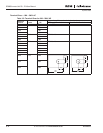
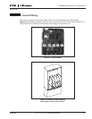
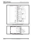
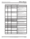
When the inverter is delivered from the factory, the control unit usually includes two basic
boards (I/O board and relay board), which are normally installed in slots A and B. On the next
pages you will find the arrangement of the control I/O and the relay terminals of the two basic
boards, the general wiring diagram and the control signal descriptions. The I/O boards
mounted at the factory are indicated in the type code. For more information on the option
boards, see the option board user manual.
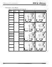
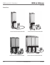
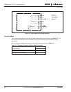
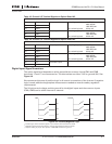
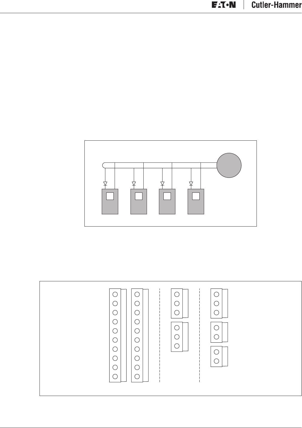
The control board can be powered externally (+24V) by connecting the external power source
to bidirectional terminal #6 (see Figure 4-5). This voltage is sufficient for parameter setting
and for keeping the fieldbus active.
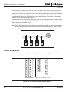
Note: If the +24V input of several inverters are connected in parallel, we recommend to use a
diode in terminal #6 to avoid the current flowing in opposite direction, which might
damage the control board.
Figure 4-3: Inverters Connected in Parallel
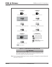
Control Wiring Details
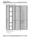
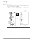
The basic control connections for boards A2 and A3 are shown in Figures 4-6 and 4-7.
You can find the signal descriptions for applications in the application manual.
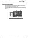
Figure 4-4: I/O Terminals of the Two Basic Boards
#
6
External
+
24V
+
–
#
7
#
6
+
–
#
7
#
6
+
–
#
7
#
6
+
–
#
7
1 2 3 4 5 6 7 8 9
21 22 23 24 25 26
21 22 23 25 26 28 29
10
Board OPT-A9 in Slot A Boards OPT-A2 and OPT-A3 in Slot B
OPT-A2
OPT-A3
11 12 13 14 15 16 17 18 19 20