SPI9000 Inverter Unit FI9 – FI14 User Manual
MN04004002E
For more information visit: www.EatonElectrical.com 5-31
September 2006
Expander Board Parameters
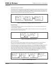
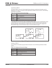
Table 5-16: Expander Board Parameters (Board OPTA9)
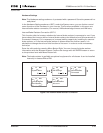
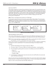
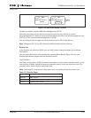
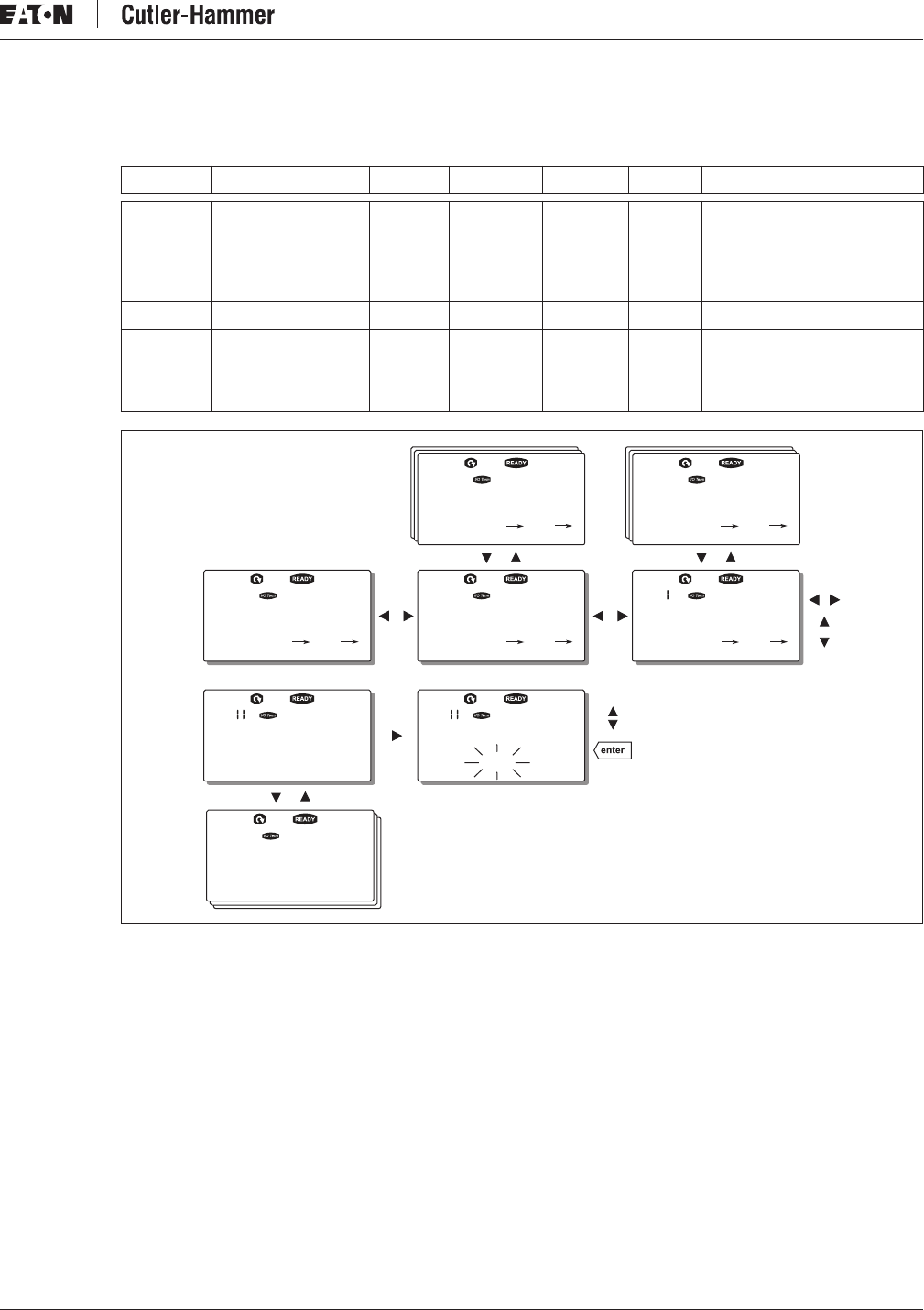
Figure 5-29: Expander Board Information Menu
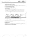
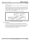
Further Keypad Functions
The control keypad contains additional application-related functions. See the application
manual for more information.
Code Parameter Min Max Default Cust Selections
P7.1.1.1 AI1 mode 1 5 3 1 = 0 to 20 mA
2 = 4 to 20 mA
3 = 0 to 10V
4 = 2 to 10V
5 = –10 to +10 V
P7.1.1.2 AI2 mode 1 5 1 See P7.1.1.1
P7.1.1.3 AO1 mode 1 4 1 1 = 0 to 20 mA
2 = 4 to 20 mA
3 = 0 to 10V
4 = 2 to 10V
Confirm Change
Change Value
Expander boards
M7
Parameters
G7.3.
G1 G5 G1 G2 P1 P4
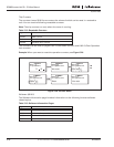
C:OPTC1
G7.3
Run
Slave address Slave address
126 126
G7.3. . G7.3. .
D:OPTC2
G1 G2
V1 V2
Monitor
Baud rate
Auto


