


SPI9000 Inverter Unit FI9 – FI14 User Manual
MN04004002E
For more information visit: www.EatonElectrical.com 4-1
September 2006
Chapter 4 — Control Wiring
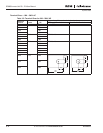
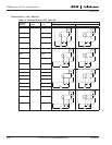
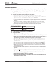
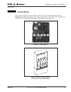
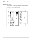
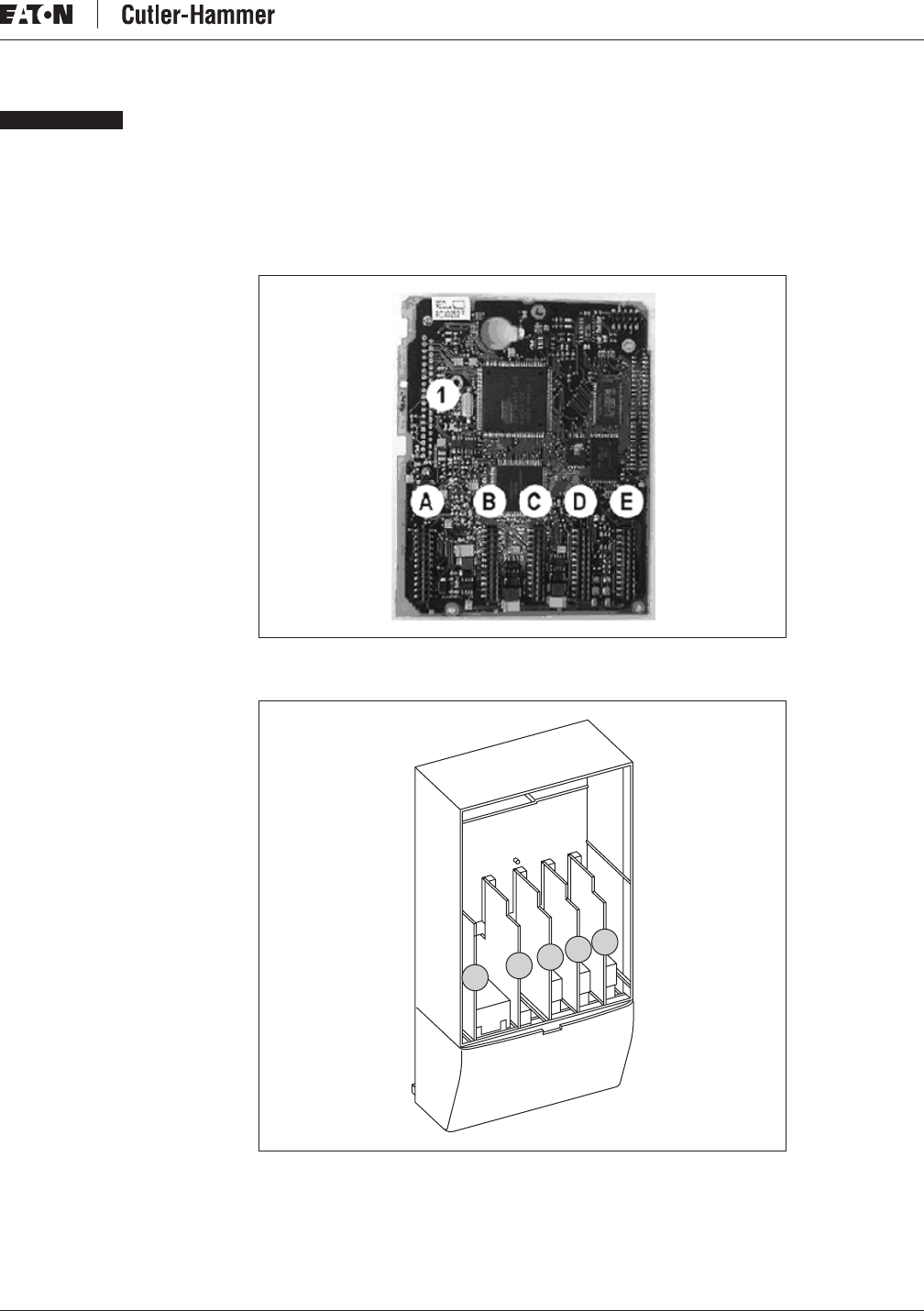
The control unit of the inverter consists of the control board and option boards (see
Figures 4-1 and 4-2) connected to the five slot connectors (A to E) on the control board. The
control board is connected to the power unit through a D connector (1).
Figure 4-1: Control Board
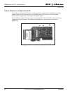
Figure 4-2: Basic and Option Board
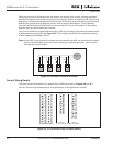
Connections of the Control Board
D
C
B
A
E